. 2017 Jun 5;216(6):1689-1703.
doi: 10.1083/jcb.201607045. Epub 2017 Apr 21.

Regulation of microtubule-associated motors drives intermediate filament network polarization

Affiliations

Regulation of microtubule-associated motors drives intermediate filament network polarization

Cécile Leduc et al. J Cell Biol. .

Abstract

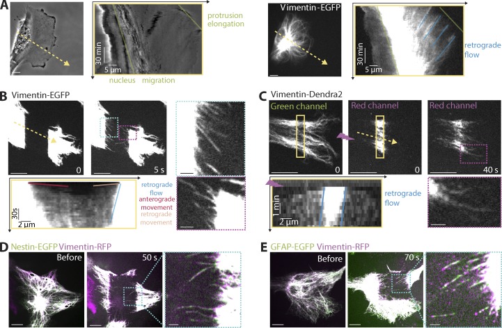
Intermediate filaments (IFs) are key players in the control of cell morphology and structure as well as in active processes such as cell polarization, migration, and mechanoresponses. However, the regulatory mechanisms controlling IF dynamics and organization in motile cells are still poorly understood. In this study, we investigate the mechanisms leading to the polarized rearrangement of the IF network along the polarity axis. Using photobleaching and photoconversion experiments in glial cells expressing vimentin, glial fibrillary acidic protein, and nestin, we show that the distribution of cytoplasmic IFs results from a continuous turnover based on the cooperation of an actin-dependent retrograde flow and anterograde and retrograde microtubule-dependent transports. During wound-induced astrocyte polarization, IF transport becomes directionally biased from the cell center toward the cell front. Such asymmetry in the transport is mainly caused by a Cdc42- and atypical PKC-dependent inhibition of dynein-dependent retrograde transport. Our results show how polarity signaling can affect the dynamic turnover of the IF network to promote the polarization of the network itself.


Figures

Figure 1.
Figure 1.
Distribution of cytoplasmic IFs in astrocytes. (A) Epifluorescence image of nestin (green), vimentin (magenta), and GFAP (yellow) immunostaining of a migrating astrocyte 10 h after wounding. The intensity profiles were obtained along the dotted arrow. Bars, 20 µm. (B) 3D structured illumination microscopy images of nestin (green), vimentin (magenta), and GFAP (yellow) immunostaining at the front of a migrating astrocyte. Kinesin depletion was used to decrease the density of IFs at the cell front, facilitating the visualization of single filaments. A higher magnification of the boxed region is shown in the middle. Fluorescence (Fluo.) intensity profiles showing the distribution of nestin, vimentin, and GFAP along a single filament (indicated by a dotted arrow in the inset) are shown on the right. Bars: (main image) 10 µm; (inset) 1 µm. a.u., arbitrary units.
Figure 2.
Figure 2.
Vimentin filament dynamics during astrocytoma random migration. (A) Phase contrast (left) and fluorescence (right) images of a motile astrocytoma cell (U373 cell line) expressing vimentin-EGFP (Video 1; total time, 120 min). (B) Still images of the vimentin network acquired 0 and 5 s after photobleaching of a vimentin-GFP– and tubulin-mCherry–expressing astrocytoma cell (Video 2; total time, 2 min; see also Fig. S1, B–D). mCherry-tubulin images are shown in Fig. S1 C. (C) Green and red fluorescence images of a vimentin-Dendra2–expressing astrocytoma cell just after (t = 0) and 40 s after photoconversion by a 405-nm flash illumination (purple) in the yellow rectangle (Video 3; total time, 2 min). Kymographs are boxed in yellow and show the fluorescence intensity profile along the yellow arrow in the corresponding image over time. The colored lines highlight the nucleus and protrusion forward movements (green), the retrograde flow (blue), and the anterograde (red) and retrograde (orange) movements of IFs on kymographs. The higher-magnification images of regions indicated by a cyan or purple dashed box are shown in the corresponding dotted line boxes. (D) Merged images of an astrocytoma coexpressing GFAP-EGFP and vimentin-RFP just before and 50 s after photobleaching with a zoom on moving filaments. (E) Merged images of an astrocytoma coexpressing nestin-EGFP and vimentin-RFP just before and 70 s after photobleaching with a zoom on filaments. Bars: (main images) 10 µm; (insets) 2 µm.
Figure 3.
Figure 3.
Vimentin interplay with actin filaments and microtubules. (A–C) Fluorescence images taken from FRAP experiments on vimentin-EGFP–expressing astrocytoma cells treated with DMSO (A), 10 µM latrunculin A (B), and 2 µM blebbistatin (C). The images were acquired 0 and 9 min after photobleaching. Kymographs are boxed in yellow and show the fluorescence intensity profile along the yellow arrows in the corresponding images over time for each condition. The higher-magnification images of regions indicated by a blue dotted box are shown in the corresponding dotted line boxes. (D) Fluorescence image of an astrocytoma cell expressing vimentin-EGFP (green) and mCherry-tubulin (magenta). Time-lapse images of the region indicated by a dotted blue box are shown on the right. Arrowheads highlight a microtubule tip, and asterisks show the tip of a vimentin IF moving along this microtubule (Video 5; total time, 12 min). (E) Fluorescence images of an astrocytoma cell expressing vimentin-EGFP and mCherry-tubulin showing EGFP fluorescence 2 min after photobleaching and mCherry fluorescence before photobleaching. The merged image and the higher-magnification image of the boxed region are shown on the right. (F) STORM image of the edge of a migrating astrocytoma cell stained for vimentin (green) merged with the corresponding epifluorescence (epi) image of the microtubule network (magenta). A higher magnification of the region indicated by a dotted line rectangle on the vimentin network is shown on the right. (G) FRAP experiment on a vimentin-EGFP–expressing astrocytoma cell treated with 10 µM nocodazole. White dashed outline indicates the cell contour. A higher magnification of the boxed region (cyan) shows single vimentin filaments moving into the bleached area from the adjacent regions. The kymograph shows the fluorescence intensity profile along the yellow arrow over time. Bars: (main images) 10 µm; (insets) 2 µm; unless otherwise indicated.
Figure 4.
Figure 4.
Regulation of kinesin-1– and dynein-1– dependent transport drives the polarization of the IF network. (A) Epifluorescence images of vimentin (green), tubulin (magenta), and DNA (blue) in migrating astrocytes (before wounding, 1 h 30 min, 4 h, and 10 h after wounding) 4 d after nucleofection with the indicated siRNAs (also see Fig. S3 A). Dashed lines indicate wound orientation. (B) Ratios between front and perinuclear vimentin fluorescence (Fluo) intensities before wounding (confluent cells) or at different times after wounding. Cells were nucleofected with the indicated siRNAs. The results are shown as means ± SEM of at least three independent experiments with ∼50 cells per time point, per condition, per repeat experiment; ∼1,800 cells were used in total. (C–E) Fluorescence images acquired 6 min after photobleaching during a FRAP experiments on vimentin-EGFP–expressing astrocytes in confluent cells (C) 1 h 30 min (D) and 8 h (E) after wounding (Video 7). Fluorescence intensity profiles along corresponding arrows show either a symmetric (C and E) or asymmetric (D) recovery of fluorescence. The higher-magnification images of regions indicated by a dotted line box are shown in corresponding dotted line boxes. Bars: (main images) 10 µm; (insets) 2 µm. Filled arrows point to the slopes observed in the fluorescence recovery profile, indicating a symmetric or asymmetric recovery of fluorescence. Note that in the case of asymmetry, the fluorescence recovery occurs only from the rear side of the photobleached area (shown by a single filled arrow). a.u., arbitrary units. (F) Percentages of cells displaying a symmetric fluorescence recovery in each condition (33–54 cells per condition in a minimum of three independent experiments). (G) Speed of the retrograde flow in each condition was extracted from the same data as in F. Means ± SEM of three independent experiments are shown. *, P < 0.05; **, P < 0.01; ***, P < 0.001; ****, P < 0.0001.
Figure 5.
Figure 5.
Vimentin transport directionality is triggered by cell polarization. (A) Merged images of vimentin (green), tubulin (magenta), and DNA (blue) of nonmigrating astrocytes plated on either 120-µm (polarized cells) or 50-µm disks (nonpolarized cells). Cells were nucleofected with the indicated siRNAs. Bars, 10 µm. (B) Ratio between peripheral and perinuclear vimentin intensity in each condition. Each experiment was repeated three times with ∼50 cells per condition and per repeat. Error bars display the SEM for the three repeats. (C and D, left) Still fluorescence (Fluo.) images (6 min after photobleaching) of vimentin-EGFP–expressing astrocytes: five to eight cells were plated on 120-µm diameter micropatterns (C), and single cells were plated on a 50-µm diameter circular micropatterns (D). Bars: (main images) 10 µm; (insets) 2 µm. (Right) Fluorescence intensity profiles along the corresponding arrows showing the fluorescence recovery at different time points after photobleaching. Filled arrows point to the slopes observed in the fluorescence recovery profile, indicating a symmetric or asymmetric recovery of fluorescence. Note that in the case of asymmetry, the fluorescence recovery occurs only from the rear side of the photobleached area (shown by a single filled arrow). a.u., arbitrary units. (E) Percentages of cells displaying a symmetric fluorescence recovery (32 polarized nonmigrating cells and 15 nonpolarized nonmigrating cells out of three and five independent experiments, respectively). (F) Quantification of the vimentin retrograde flow. Error bars display SEM for the three repeats with 32 and 15 cells per condition, respectively. *, P < 0.05; **, P < 0.01; ***, P < 0.001. (G) Schematics of IF dynamics during cell polarization and migration. Arrows correspond with colored labels on the right.
Figure 6.
Figure 6.
Vimentin dynamics is regulated by Cdc42 during cell polarization. (A) Merged images of vimentin (green), tubulin (magenta), and DNA (blue) of astrocytes before or 1 h 30 min after wounding. Cells were nucleofected with indicated siRNAs (also see Fig. S3 B). The orientation of the wound is shown with dashed lines. Bars, 20 µm. (B, left) Still fluorescence (Fluo.) images 3 min after photobleaching from a FRAP experiment performed with vimentin-EGFP–expressing astrocytes 1 h 30 min after wounding. Wounding was done 4 d after cell nucleofection with the indicated siRNAs (see Video 8 for small interfering Cdc42). The contrast was increased in the zoom of Cdc42-depleted cell to better show the emergence of vimentin filaments in the photobleached region. (Right) fluorescence intensity profiles showing the fluorescence recovery at different time points after photobleaching. (C) Percentages of cells displaying a symmetric FRAP 1 h 30 min after wounding. Cells were nucleofected with the indicated siRNA or treated with DMSO, ML141 (inhibitor of Cdc42; 10 µM added 1 h before wounding), and NSC23761 (inhibitor of Rac1; 50 µM added 1 h before wounding; 44–66 cells per condition with a minimum of three independent experiments). (D, left) Still fluorescence images acquired 3 min after photobleaching of vimentin-EGFP–expressing astrocytes 10 h after wounding. Control or Cdc42-depleted cells were left treated with DMSO or with bradykinin (10 µM) 1 h before the FRAP experiment. (Right) Fluorescence intensity profiles along the corresponding arrows showing the fluorescence recovery at different time points after photobleaching. Filled arrows point to the slopes observed in the fluorescence recovery profile, indicating a symmetric or asymmetric recovery of fluorescence. Note that in the case of asymmetry, the fluorescence recovery occurs only from the rear side of the photobleached area (shown by a single filled arrow). (B and D) Bars: (main images) 10 µm; (insets) 2 µm. a.u., arbitrary units. (E) Percentages of cells displaying a symmetric profile of FRAP after 10 h of migration. Control or Cdc42-depleted cells were left treated with DMSO or bradykinin (10 µM; 1 h; 37–60 cells per condition with a minimum of three independent experiments). (F) Quantification of the vimentin retrograde flow in the experiments described in E. Error bars display SEM for the three repeats. *, P < 0.05; ***, P < 0.001. (G) Schematics representing the mechanisms involved in IF dynamics after Cdc42 activation by Bradykinin treatment. Arrows correspond with colored labels on the right.
Figure 7.
Figure 7.
Vimentin dynamics are regulated by aPKC during cell polarization. (A) Merged images of vimentin (green), tubulin (magenta), γ-tubulin (γ-tub; yellow), and DNA (blue) of astrocytes 4 d after transfection with indicated siRNAs (also see Fig. S3 C). Dashed lines indicate wound orientation. Bars, 20 µm. (B, left) Still fluorescence (Fluo.) images 3 min after photobleaching of vimentin-EGFP–expressing astrocytes 1 h 30 min after wounding. Cells were nucleofected with the indicated siRNAs (see Video 9 for small interfering aPKC [si-aPKC]). (Right) Line profiles showing the FRAP. (C and E) Percentages of cells displaying a symmetric profile of FRAP 1 h 30 min after wounding. Cells were nucleofected with the indicated siRNA or constructs and then were left untreated or treated with DMSO, PKCζ pseudosubstrate (PS; inhibitor of PKCζ; 10 µM was added 1 h before wounding), and wiskostatin (inhibitor of N-WASp; 2 µM was added 1 h after wounding). Statistics include 36–74 cells per condition from a minimum of three independent experiments. (D, left) Still fluorescence images acquired 3 min after photobleaching of Cdc42-depleted astrocytes expressing vimentin-RFP and either EGFP or PKCζ-EGFP (Video 10) 1 h 30 min after wounding. (Right) Line profiles showing the FRAP. Filled arrows point to the slopes observed in the fluorescence recovery profile, indicating a symmetric or asymmetric recovery of fluorescence. Note that in the case of asymmetry, the fluorescence recovery occurs only from the rear side of the photobleached area (shown by a single filled arrow). Bars: (main images) 10 µm; (insets) 2 µm. a.u., arbitrary units. (F) Schematic diagram showing the “front” polarity signaling triggering the polarized rearrangements of IFs and microtubules during astrocyte polarization. MT, microtubule.

Comment in

  • Intermediate filaments join the action.
    Leduc C, Etienne-Manneville S. Leduc C, et al. Cell Cycle. 2017 Aug 3;16(15):1389-1390. doi: 10.1080/15384101.2017.1345230. Epub 2017 Jul 19. Cell Cycle. 2017. PMID: 28722513 Free PMC article. No abstract available.

References

    1. Bhattacharya R., Gonzalez A.M., Debiase P.J., Trejo H.E., Goldman R.D., Flitney F.W., and Jones J.C.. 2009. Recruitment of vimentin to the cell surface by β3 integrin and plectin mediates adhesion strength. J. Cell Sci. 122:1390–1400. 10.1242/jcs.043042 - DOI - PMC - PubMed
    1. Burgstaller G., Gregor M., Winter L., and Wiche G.. 2010. Keeping the vimentin network under control: Cell–matrix adhesion-associated plectin 1f affects cell shape and polarity of fibroblasts. Mol. Biol. Cell. 21:3362–3375. 10.1091/mbc.E10-02-0094 - DOI - PMC - PubMed
    1. Carlier M.F., Pernier J., Montaville P., Shekhar S., and Kühn S.. Cytoskeleton Dynamics and Motility group . 2015. Control of polarized assembly of actin filaments in cell motility. Cell. Mol. Life Sci. 72:3051–3067. 10.1007/s00018-015-1914-2 - DOI - PMC - PubMed
    1. Chan W., Kozma R., Yasui Y., Inagaki M., Leung T., Manser E., and Lim L.. 2002. Vimentin intermediate filament reorganization by Cdc42: involvement of PAK and p70 S6 kinase. Eur. J. Cell Biol. 81:692–701. 10.1078/0171-9335-00281 - DOI - PubMed
    1. Chu Y., Hughes S., and Chan-Ling T.. 2001. Differentiation and migration of astrocyte precursor cells and astrocytes in human fetal retina: relevance to optic nerve coloboma. FASEB J. 15:2013–2015. - PubMed

Publication types

MeSH terms