

csiLSFM combines light-sheet fluorescence microscopy and coherent structured illumination for a lateral resolution below 100 nm
- PMID: 28438995
- PMCID: PMC5441750
- DOI: 10.1073/pnas.1609278114
csiLSFM combines light-sheet fluorescence microscopy and coherent structured illumination for a lateral resolution below 100 nm
Abstract
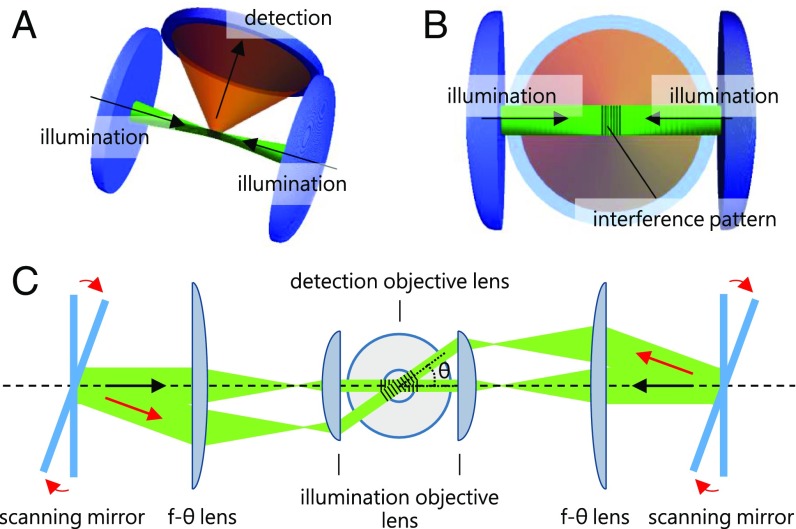
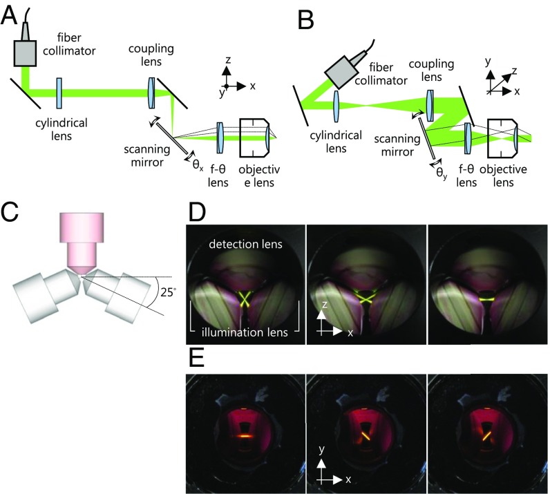
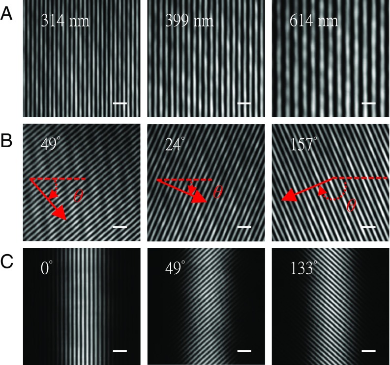
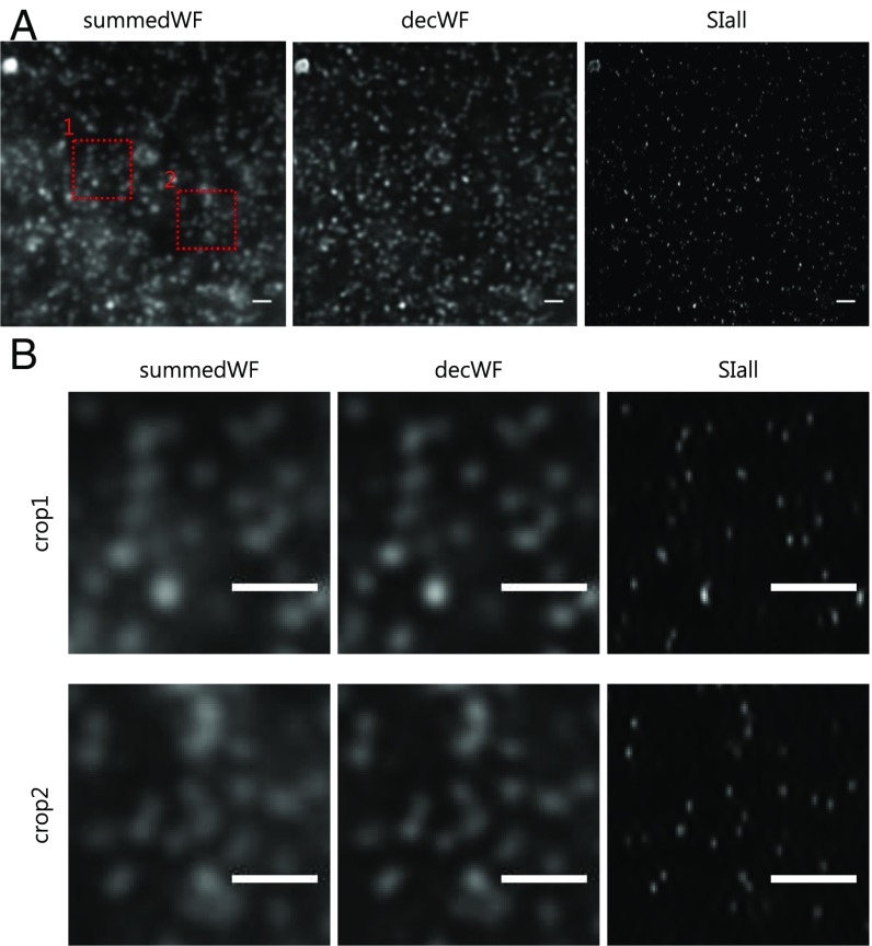
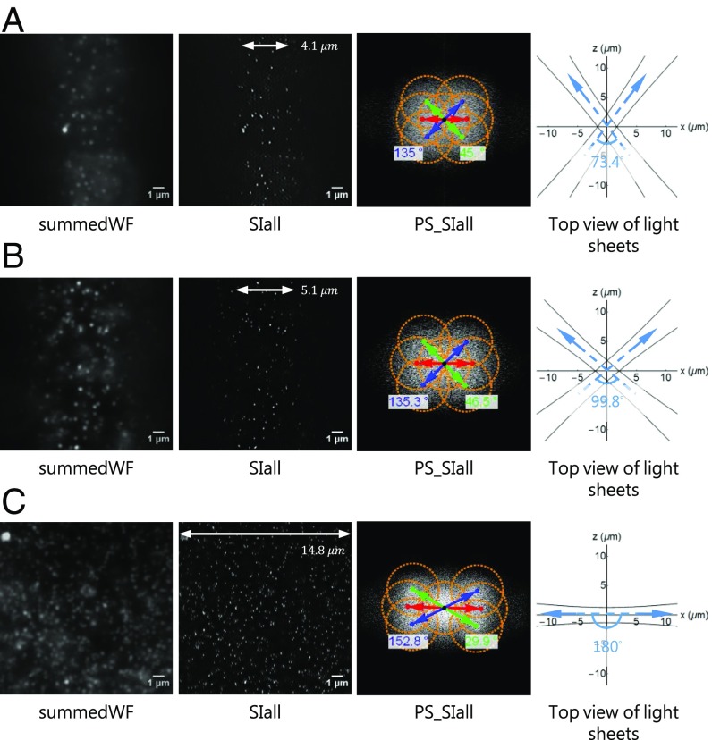
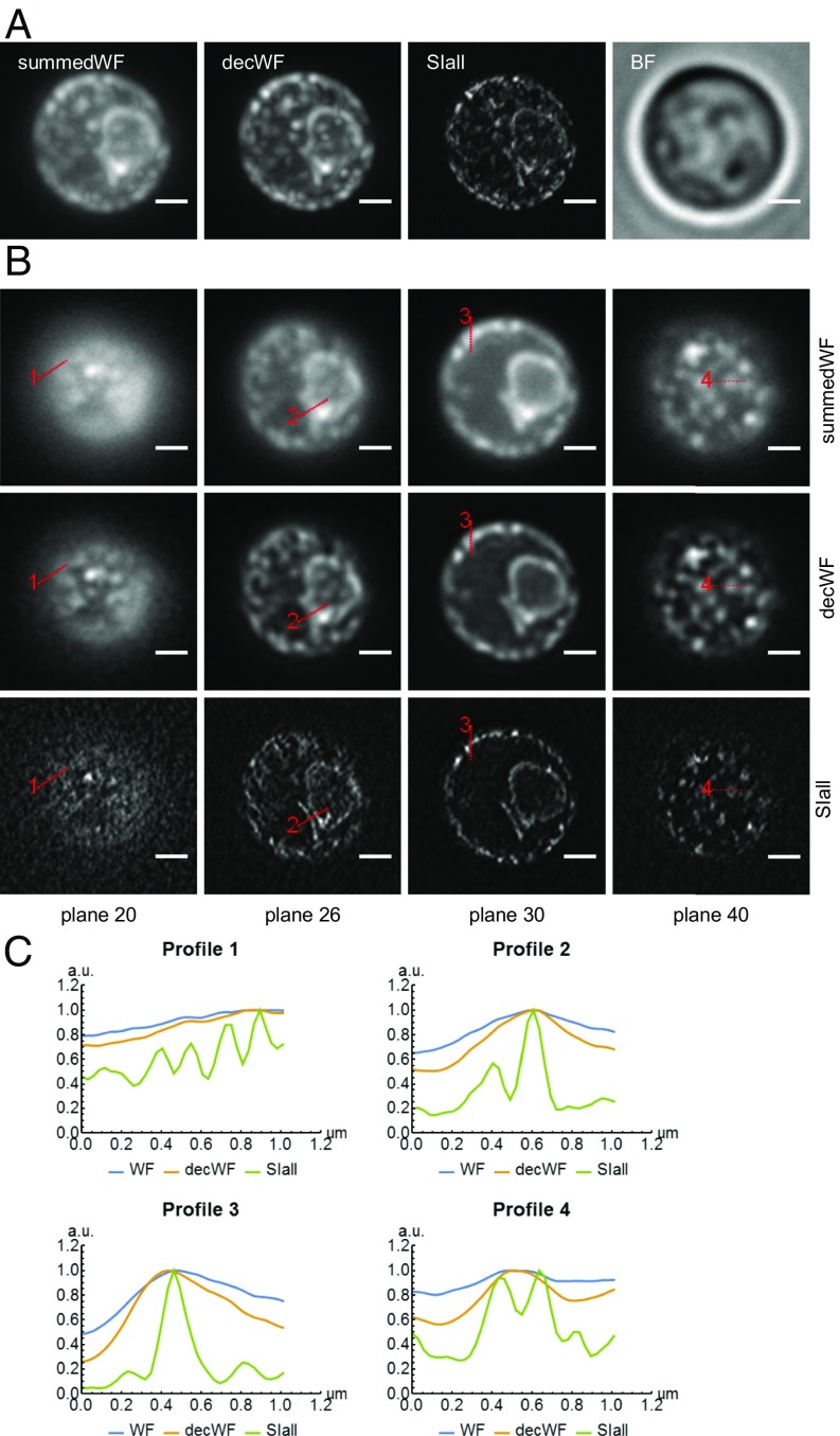
Light-sheet-based fluorescence microscopy (LSFM) features optical sectioning in the excitation process. It minimizes fluorophore bleaching as well as phototoxic effects and provides a true axial resolution. The detection path resembles properties of conventional fluorescence microscopy. Structured illumination microscopy (SIM) is attractive for superresolution because of its moderate excitation intensity, high acquisition speed, and compatibility with all fluorophores. We introduce SIM to LSFM because the combination pushes the lateral resolution to the physical limit of linear SIM. The instrument requires three objective lenses and relies on methods to control two counterpropagating coherent light sheets that generate excitation patterns in the focal plane of the detection lens. SIM patterns with the finest line spacing in the far field become available along multiple orientations. Flexible control of rotation, frequency, and phase shift of the perfectly modulated light sheet are demonstrated. Images of beads prove a near-isotropic lateral resolution of sub-100 nm. Images of yeast endoplasmic reticulum show that coherent structured illumination (csi) LSFM performs with physiologically relevant specimens.
Keywords: LSFM; SIM; SPIM; light sheet; structured illumination.
Conflict of interest statement
The authors declare no conflict of interest.
Figures
Similar articles
-
Resolution doubling in light-sheet microscopy via oblique plane structured illumination.Nat Methods. 2022 Nov;19(11):1419-1426. doi: 10.1038/s41592-022-01635-8. Epub 2022 Oct 24. Nat Methods. 2022. PMID: 36280718 Free PMC article.
-
Light Sheet Fluorescence Microscopy (LSFM).Curr Protoc Cytom. 2015 Jan 5;71:12.37.1-12.37.15. doi: 10.1002/0471142956.cy1237s71. Curr Protoc Cytom. 2015. PMID: 25559221 Free PMC article.
-
πSPIM: high NA high resolution isotropic light-sheet imaging in cell culture dishes.Sci Rep. 2016 Sep 13;6:32880. doi: 10.1038/srep32880. Sci Rep. 2016. PMID: 27619647 Free PMC article.
-
Technical implementations of light sheet microscopy.Microsc Res Tech. 2018 Sep;81(9):941-958. doi: 10.1002/jemt.22981. Epub 2018 Jan 11. Microsc Res Tech. 2018. PMID: 29322581 Review.
-
Light sheet microscopy and live imaging of plants.J Microsc. 2016 Aug;263(2):158-64. doi: 10.1111/jmi.12393. Epub 2016 Mar 28. J Microsc. 2016. PMID: 27019306 Review.
Cited by
-
Tunable structured illumination light sheet microscopy for background rejection and imaging depth in minimally processed tissues.J Biomed Opt. 2019 Apr;24(4):1-6. doi: 10.1117/1.JBO.24.4.046501. J Biomed Opt. 2019. PMID: 30968649 Free PMC article.
-
Fluorescent toys 'n' tools lighting the way in fungal research.FEMS Microbiol Rev. 2021 Sep 8;45(5):fuab013. doi: 10.1093/femsre/fuab013. FEMS Microbiol Rev. 2021. PMID: 33595628 Free PMC article.
-
Super-Resolution Imaging of Neuronal Structures with Structured Illumination Microscopy.Bioengineering (Basel). 2023 Sep 13;10(9):1081. doi: 10.3390/bioengineering10091081. Bioengineering (Basel). 2023. PMID: 37760183 Free PMC article.
-
Resolution doubling in light-sheet microscopy via oblique plane structured illumination.Nat Methods. 2022 Nov;19(11):1419-1426. doi: 10.1038/s41592-022-01635-8. Epub 2022 Oct 24. Nat Methods. 2022. PMID: 36280718 Free PMC article.
-
GPU-accelerated real-time reconstruction in Python of three-dimensional datasets from structured illumination microscopy with hexagonal patterns.Philos Trans A Math Phys Eng Sci. 2021 Jun 14;379(2199):20200162. doi: 10.1098/rsta.2020.0162. Epub 2021 Apr 26. Philos Trans A Math Phys Eng Sci. 2021. PMID: 33896199 Free PMC article.
References
-
- Stelzer EHK. Light-sheet fluorescence microscopy for quantitative biology. Nat Methods. 2015;12:23–26. - PubMed
-
- Huisken J, Swoger J, Del Bene F, Wittbrodt J, Stelzer EHK. Optical sectioning deep inside live embryos by selective plane illumination microscopy. Science. 2004;305:1007–1009. - PubMed
-
- Keller PJ, Schmidt AD, Wittbrodt J, Stelzer EHK. Digital scanned laser light-sheet fluorescence microscopy (DSLM) of zebrafish and Drosophila embryonic development. Cold Spring Harb Protoc. 2011;2011:1235–1243. - PubMed
-
- Strobl F, Stelzer EHK. Non-invasive long-term fluorescence live imaging of Tribolium castaneum embryos. Development. 2014;141:2331–2338. - PubMed
-
- Strobl F, Schmitz A, Stelzer EHK. Live imaging of Tribolium castaneum embryonic development using light-sheet-based fluorescence microscopy. Nat Protoc. 2015;10:1486–1507. - PubMed
Publication types
MeSH terms
LinkOut - more resources
Full Text Sources
Other Literature Sources
