Review
. 2017 Apr;29(2):115-145.
doi: 10.1080/09540261.2017.1305949. Epub 2017 Apr 26.

The development and modelling of devices and paradigms for transcranial magnetic stimulation

Affiliations
Review

The development and modelling of devices and paradigms for transcranial magnetic stimulation

Stefan M Goetz et al. Int Rev Psychiatry. 2017 Apr.

Abstract

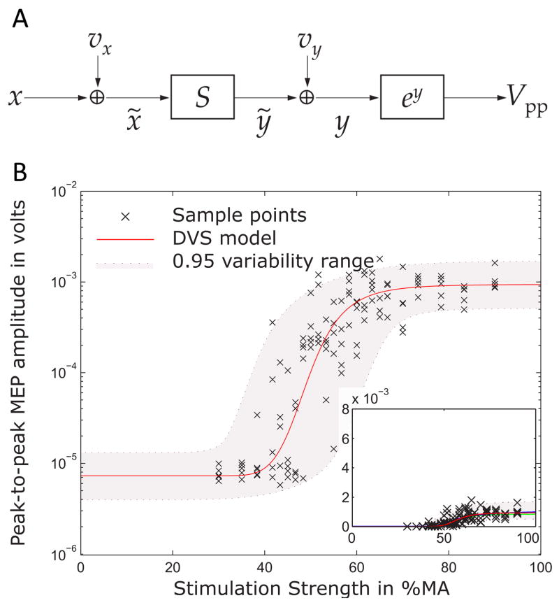
Magnetic stimulation is a non-invasive neurostimulation technique that can evoke action potentials and modulate neural circuits through induced electric fields. Biophysical models of magnetic stimulation have become a major driver for technological developments and the understanding of the mechanisms of magnetic neurostimulation and neuromodulation. Major technological developments involve stimulation coils with different spatial characteristics and pulse sources to control the pulse waveform. While early technological developments were the result of manual design and invention processes, there is a trend in both stimulation coil and pulse source design to mathematically optimize parameters with the help of computational models. To date, macroscopically highly realistic spatial models of the brain, as well as peripheral targets, and user-friendly software packages enable researchers and practitioners to simulate the treatment-specific and induced electric field distribution in the brains of individual subjects and patients. Neuron models further introduce the microscopic level of neural activation to understand the influence of activation dynamics in response to different pulse shapes. A number of models that were designed for online calibration to extract otherwise covert information and biomarkers from the neural system recently form a third branch of modelling.

Keywords: TMS; Transcranial magnetic stimulation; biophysical modelling; medical technology; neuromodulation; neuroscience; neurostimulation.


Figures

Figure 1
Figure 1
A. Early repetitive stimulators such as the depicted monophasic stimulator with maximum repetition rates of more than 30 Hz, peak voltage of 5,000 V, and variable rise-time provided by adjustable capacitance between 40 μF and 200 μF allowed neuromuscular magnetic stimulation in the periphery and neuromodulatory protocols in the brain for the first time (Schmid, et al., 1993). B. Structure of a modern figure-of-eight coil, which is typically formed by a conductor loop, here a copper band, between the two pieces of the casing. The coil incorporates at least one, often two temperature sensors near the conductor that terminate stimulation when the coil exceeds the safe temperature range. It is usually filled with hardening resin for mechanical robustness, thermal conductivity, and electrical safety (modified from (Mould, 1998)).
Figure 2
Figure 2
Example illustrations of TMS coils (top) and the corresponding induced electric field distributions simulated in a spherical model (bottom). A. 70-mm figure-of-eight coil (The Magstim Ltd., Whitland, Wales). B. Figure-of-eight coil with soft-magnetic back-plate. C. C-core coil (Neuronetics, Inc., Malvern, PA). D. Minimum energy eccentric coil (Knäulein & Weyh, 1996). E. Cloverleaf coil. F. Multi-focal multi-layer coil, composed of two orthogonal layers of cloverleaf coils, a circular coil, and two orthogonal layers of figure-8 coils.
Figure 3
Figure 3
Different approaches for improving stimulation coils with soft-magnetic materials: A. Commercial C-core coil (Neuronetics, Inc., Malvern, PA) and B. core-enhanced figure-of-eight coil with magnetic back-plate to reduce the field energy of the field as presented by A. Barker (A. T. Barker, 2001).
Figure 4
Figure 4
Actual implementations of early magnetic stimulation coils: A. and B. early academic coils with C-shaped cores of a cobalt-steel alloy with high permeability and saturation level (Lorenzen & Weyh, 1992; Schmid, et al., 1993) (Courtesy of Dr. Thomas Weyh). C. Eccentric figure-of-eight coil. D. Cloverleaf coil (Courtesy of Dr. Eric Wassermann).
Figure 5
Figure 5
A. First magnetic stimulator built by Drs. M. Polson and A. Barker in 1982, which was a single-pulse device primarily tested in animals and peripherally (Polson, et al., 1982) (Courtesy of Dr. Michael Polson). B. Modern repetitive pulse source with power supply, high-voltage pulse train, and control unit (Mag&More GmbH, Munich, Germany).
Figure 6
Figure 6
Circuit topologies (left column) and typical pulse shapes (right column) of typical magnetic stimulation pulse sources. A. Monophasic stimulator, B. Biphasic and polyphasic stimulator, C. controllable parameter TMS (cTMS), D. Modular pulse synthesizer.
Figure 7
Figure 7
Coil models with: A. bulk conductor, B. individual turns with idealized line current, and C. individual turns with 3D representation of windings, demonstrating the increasing level of detail in induced-field modeling.
Figure 8
Figure 8
Realistic head model of TMS: A. Figure-of-eight coil placed over the left primary motor cortex. B. Induced electric field distribution showing the effect of a focus spread out over several gyri. C. A coronal view at the level of the TMS hotspot, in a head model that assumes isotropic tissue conductivity for the white matter. D. The same view as in C in a head model that incorporated white matter anisotropy derived from diffusion tensor imaging data. The model shows slightly deeper reach of the electric field.
Figure 9
Figure 9
Model for describing the stimulus–response behavior of motor-evoked potentials. A. Each stimulus with strength x that activates the motor cortical target is perturbed by a variability source vx, which describes ongoing endogenous neuromodulation and incoming signals to the activated neurons. A summation S represents the recruitment of the many parallel units. A second variability source vy and an exponential function together describe the multiplicative output-side variability, which is caused by effects in the periphery, such as cellular fluctuations of calcium concentrations and fatigue, and measurement noise. B. The model (line and grey band) well describes the experimental behavior given by the crosses and allows splitting variability into its contributions to detect endogenous neuromodulation of the stimulated neurons in real-time.

References

    1. Agudelo-Toro A, Neef A. Computationally efficient simulation of electrical activity at cell membranes interacting with self-generated and externally imposed electric fields. Journal of Neural Engineering. 2013;10(2):026019. - PubMed
    1. Al-Mutawaly N, de Bruin H. Designing and constructing a magnetic stimulator: theoretical and practical considerations. Proc IEEE Eng Biol Med Eng EMBC. 2001;23:881–884.
    1. Al-Mutawaly N, Findlay RD. A novel coil design for magnetic nerve stimulation. Proc IEEE Can Conf Elec Comp Eng. 1998;2:669–672.
    1. Alavi SMM, Goetz SM, Peterchev AV. Fast curve fitting using optimal sampling. 2016 under review.
    1. Aleman A. Use of Repetitive Transcranial Magnetic Stimulation for Treatment in Psychiatry. Clin Psychopharmacol Neurosci. 2013;11(2):53–59. - PMC - PubMed

Publication types

MeSH terms