

Clinical Study of Orthogonal-View Phase-Matched Digital Tomosynthesis for Lung Tumor Localization
- PMID: 28449625
- PMCID: PMC5547009
- DOI: 10.1177/1533034617705716
Clinical Study of Orthogonal-View Phase-Matched Digital Tomosynthesis for Lung Tumor Localization
Abstract
Background and purpose: Compared to cone-beam computed tomography, digital tomosynthesis imaging has the benefits of shorter scanning time, less imaging dose, and better mechanical clearance for tumor localization in radiation therapy. However, for lung tumors, the localization accuracy of the conventional digital tomosynthesis technique is affected by the lack of depth information and the existence of lung tumor motion. This study investigates the clinical feasibility of using an orthogonal-view phase-matched digital tomosynthesis technique to improve the accuracy of lung tumor localization.
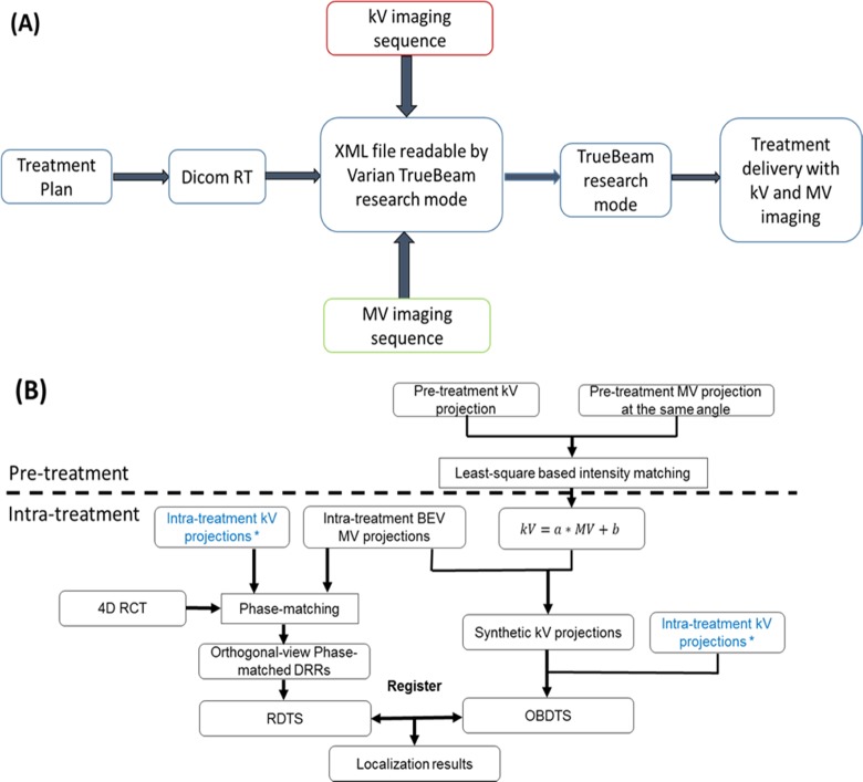
Materials and methods: The proposed orthogonal-view phase-matched digital tomosynthesis technique benefits from 2 major features: (1) it acquires orthogonal-view projections to improve the depth information in reconstructed digital tomosynthesis images and (2) it applies respiratory phase-matching to incorporate patient motion information into the synthesized reference digital tomosynthesis sets, which helps to improve the localization accuracy of moving lung tumors. A retrospective study enrolling 14 patients was performed to evaluate the accuracy of the orthogonal-view phase-matched digital tomosynthesis technique. Phantom studies were also performed using an anthropomorphic phantom to investigate the feasibility of using intratreatment aggregated kV and beams' eye view cine MV projections for orthogonal-view phase-matched digital tomosynthesis imaging. The localization accuracy of the orthogonal-view phase-matched digital tomosynthesis technique was compared to that of the single-view digital tomosynthesis techniques and the digital tomosynthesis techniques without phase-matching.
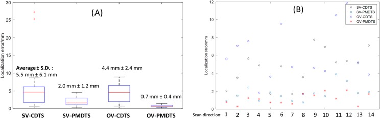
Results: The orthogonal-view phase-matched digital tomosynthesis technique outperforms the other digital tomosynthesis techniques in tumor localization accuracy for both the patient study and the phantom study. For the patient study, the orthogonal-view phase-matched digital tomosynthesis technique localizes the tumor to an average (± standard deviation) error of 1.8 (0.7) mm for a 30° total scan angle. For the phantom study using aggregated kV-MV projections, the orthogonal-view phase-matched digital tomosynthesis localizes the tumor to an average error within 1 mm for varying magnitudes of scan angles.
Conclusion: The pilot clinical study shows that the orthogonal-view phase-matched digital tomosynthesis technique enables fast and accurate localization of moving lung tumors.
Keywords: MV imaging; digital tomosynthesis; orthogonal-view; phase-matched DTS; tumor localization.
Conflict of interest statement
Figures


Similar articles
-
Respiration-phase-matched digital tomosynthesis imaging for moving target verification: a feasibility study.Med Phys. 2013 Jul;40(7):071723. doi: 10.1118/1.4810921. Med Phys. 2013. PMID: 23822427
-
A dual-view digital tomosynthesis imaging technique for improved chest imaging.Med Phys. 2015 Sep;42(9):5238-51. doi: 10.1118/1.4928214. Med Phys. 2015. PMID: 26328973 Free PMC article.
-
A limited-angle intrafraction verification (LIVE) system for radiation therapy.Med Phys. 2014 Feb;41(2):020701. doi: 10.1118/1.4861820. Med Phys. 2014. PMID: 24506590
-
Slow gantry rotation acquisition technique for on-board four-dimensional digital tomosynthesis.Med Phys. 2010 Feb;37(2):921-33. doi: 10.1118/1.3285291. Med Phys. 2010. PMID: 20229901
-
Image acquisition optimization of a limited-angle intrafraction verification (LIVE) system for lung radiotherapy.Med Phys. 2018 Jan;45(1):340-351. doi: 10.1002/mp.12647. Epub 2017 Nov 30. Med Phys. 2018. PMID: 29091287 Free PMC article.
Cited by
-
Model evaluation of rapid 4-dimensional lung tomosynthesis.Adv Radiat Oncol. 2018 Mar 8;3(3):431-438. doi: 10.1016/j.adro.2018.03.001. eCollection 2018 Jul-Sep. Adv Radiat Oncol. 2018. PMID: 30202810 Free PMC article.
-
An unsupervised 2D-3D deformable registration network (2D3D-RegNet) for cone-beam CT estimation.Phys Med Biol. 2021 Mar 24;66(7):10.1088/1361-6560/abe9f6. doi: 10.1088/1361-6560/abe9f6. Phys Med Biol. 2021. PMID: 33631734 Free PMC article.
-
Breathing-Adapted Imaging Techniques for Rapid 4-Dimensional Lung Tomosynthesis.Adv Radiat Oncol. 2023 Jan 18;8(4):101173. doi: 10.1016/j.adro.2023.101173. eCollection 2023 Jul-Aug. Adv Radiat Oncol. 2023. PMID: 36852404 Free PMC article.
-
Prior frequency guided diffusion model for limited angle (LA)-CBCT reconstruction.Phys Med Biol. 2024 Jun 26;69(13):135008. doi: 10.1088/1361-6560/ad580d. Phys Med Biol. 2024. PMID: 38870947 Free PMC article.
-
Real-time liver motion estimation via deep learning-based angle-agnostic X-ray imaging.Med Phys. 2023 Nov;50(11):6649-6662. doi: 10.1002/mp.16691. Epub 2023 Sep 13. Med Phys. 2023. PMID: 37922461 Free PMC article.
References
-
- Dawson LA, Jaffray DA. Advances in image-guided radiation therapy. J Clin Oncol. 2007;25(8):938–946. - PubMed
-
- Jaffray DA, Siewerdsen JH. Cone-beam computed tomography with a flat-panel imager: initial performance characterization. Med Phys. 2000;27(6):1311–1323. - PubMed
-
- Letourneau D, Wong JW, Oldham M, et al. Cone-beam-CT guided radiation therapy: technical implementation. Radiother Oncol. 2005;75(3):279–286. - PubMed
-
- Godfrey DJ, Yin FF, Oldham M, Yoo S, Willett C. Digital tomosynthesis with an on-board kilovoltage imaging device. Int J Radiat Oncol Biol Phys. 2006;65(1):8–15. - PubMed
-
- Wu QJ, Godfrey DJ, Wang Z, et al. On-board patient positioning for head-and-neck IMRT: comparing digital tomosynthesis to kilovoltage radiography and cone-beam computed tomography. Int J Radiat Oncol Biol Phys. 2007;69(2):598–606. - PubMed
Grants and funding
LinkOut - more resources
Full Text Sources
Other Literature Sources
