. 2017 Aug 1;118(2):1055-1069.
doi: 10.1152/jn.00086.2017. Epub 2017 May 3.

Inferring neuronal network functional connectivity with directed information

Affiliations

Inferring neuronal network functional connectivity with directed information

Zhiting Cai et al. J Neurophysiol. .

Abstract

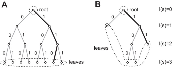
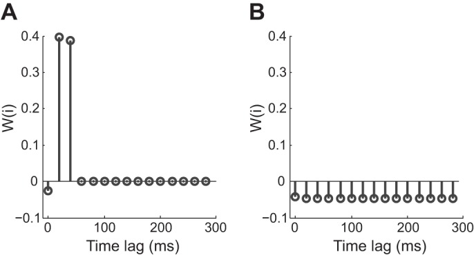
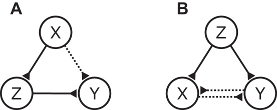
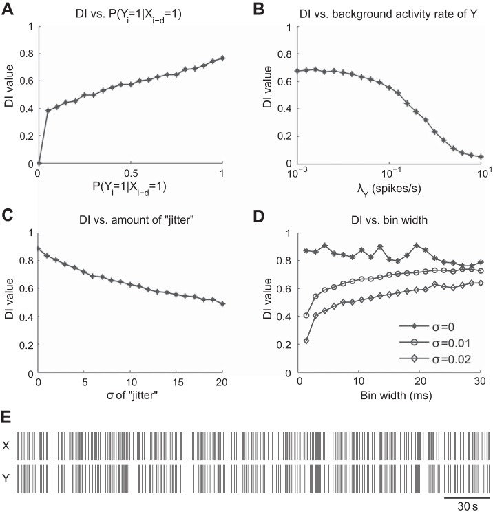
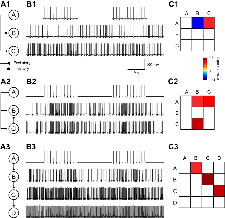
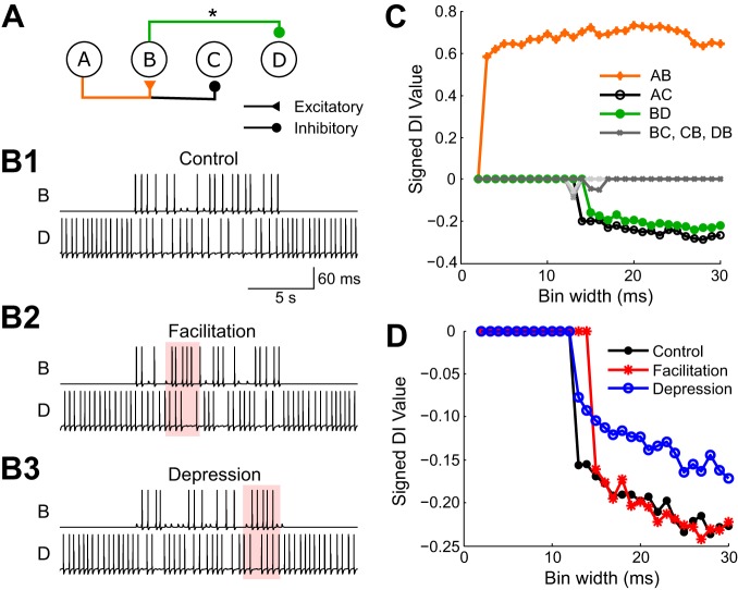
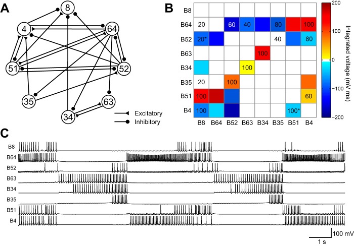
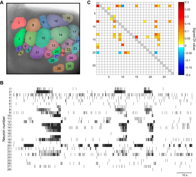
A major challenge in neuroscience is to develop effective tools that infer the circuit connectivity from large-scale recordings of neuronal activity patterns. In this study, context tree maximizing (CTM) was used to estimate directed information (DI), which measures causal influences among neural spike trains in order to infer putative synaptic connections. In contrast to existing methods, the method presented here is data driven and can readily identify both linear and nonlinear relations between neurons. This CTM-DI method reliably identified circuit structures underlying simulations of realistic conductance-based networks. It also inferred circuit properties from voltage-sensitive dye recordings of the buccal ganglion of Aplysia. This method can be applied to other large-scale recordings as well. It offers a systematic tool to map network connectivity and to track changes in network structure such as synaptic strengths as well as the degrees of connectivity of individual neurons, which in turn could provide insights into how modifications produced by learning are distributed in a neural network.NEW & NOTEWORTHY This study brings together the techniques of voltage-sensitive dye recording and information theory to infer the functional connectome of the feeding central pattern generating network of Aplysia. In contrast to current statistical approaches, the inference method developed in this study is data driven and validated by conductance-based model circuits, can distinguish excitatory and inhibitory connections, is robust against synaptic plasticity, and is capable of detecting network structures that mediate motor patterns.

Keywords: Aplysia californica; buccal ganglion; context tree maximizing; directed information; functional connectivity.


Figures

Fig. 1.
Fig. 1.
A binary context tree structure with maximum depth 3. A: a complete tree with leaves associated with all possible 23 = 8 contexts. All contexts are equally long with 3 digits. The highlighted path refers to (Yn-3 = 0, Yn-2 = 1, Yn-1 = 1), which also shows that the branch segment closer to the root corresponds to a newer sample (yn-1) and the segment closer to the leaf corresponds to an older one (yn-3). B: a trimmed tree with only 4 contexts. Note that any trimmed branch cannot be a suffix of another branch. In this case, both context …011 and context …111 are mapped to the same branch—the highlighted branch …11.
Fig. 2.
Fig. 2.
Synaptic profiles illustrating the time course of the synaptic action and distinguishing excitatory vs. inhibitory synaptic actions. A: profile of synapse AB from the network illustrated in Fig. 6A. The bin width used in this example was 10 ms. The influence from A to B is fast and strong. The values are positive, which indicates that the synapse is excitatory. B: profile of synapse BD from Fig. 6A. The influence from B to D is negative, suggesting an inhibitory connection. It is weak yet has a longer duration compared with AB.
Fig. 3.
Fig. 3.
Two fundamental types of indirect connections. A: proxy configuration. The path of information flow is from X to Z to Y, yet a false connection from X to Y can be detected. B: cascade configuration. Neuron Z is driving neurons X and Y through 2 different paths, and a false connection can be detected between X and Y.
Fig. 4.
Fig. 4.
Trends of normalized DI tested under the sparse Poisson spiking model. Parameters such as synaptic strength, background activity rate of the postsynaptic neuron, amount of “jitter” for postsynaptic spikes, and bin width were examined. A: relationship between DI and varying levels of synaptic strength. Synaptic strength was varied by changing the probability of a postsynaptic spike being elicited after a presynaptic spike. As predicted, DI value increases with a stronger synapse when the baseline activity level in Y is kept constant. B: relationship between baseline activity level λY of Y and DI. The value of DI decreases as the baseline activity in Y increases. C: relationship between the variance of the time course of the synaptic action and DI. The value of DI is inversely related to the variance of the time course. D: relationship between bin width and DI for different levels of “jitter.” A large drop in DI can be observed for σ ≥ 0.01 for small bin widths (≤3 ms). However, relatively small changes in DI can be seen for bin widths ≥ 10 ms. At σ = 0, DI remains high regardless of the size of the bin width. E: sample spike trains generated by the Poisson spiking model. λY = 0.1 and other parameters are the same as the model in B.
Fig. 5.
Fig. 5.
DI correctly inferred the connectivity in 3 simple networks. A1: neuron A inhibits neuron B and excites neuron C. A2: a network with convergence of a direct connection and a disynaptic connection, where neuron A excites neurons B and C and neuron C excites B. A3: a chain of feedforward excitation from neuron A to neuron D. B: simulated membrane potential for each neuron within the corresponding network in A. Each trace corresponds to the adjacent neuron in A. C: DI values inferred from the spike activity. A row is a presynaptic neuron, whereas a column is a postsynaptic neuron. Warm colors represent excitatory connections, whereas cool colors represent inhibitory connections. Note that DI values are always positive. Signs determined with the method introduced in Reconstructing the Synaptic Profile are attached to the DI values for ease of visualization.
Fig. 6.
Fig. 6.
DI tested on a network with synaptic plasticity. A: a neural circuit in which neuron A excites neuron B and inhibits neuron C. Neuron B inhibits neuron D. Facilitation or depression was added to synapse BD (marked with an asterisk). B: sample traces generated by the circuit in three conditions: control (B1), facilitated (B2), and depressed (B3). The area of interest where the effects of plasticity can be observed is marked in pink. In B2 the strength of the synapse increases where spikes come in quick succession, whereas in B3 the strength of the synapse decreases where spikes closely follow each other. C: signed DI values plotted against bin widths for condition B2 with facilitation. D: signed DI values for synapse BD against different bin widths for all 3 different conditions.
Fig. 7.
Fig. 7.
Testing a conductance-based model of the central pattern generator (CPG) in the buccal ganglion of Aplysia. A: connections of the CPG model. B: the same model network represented in a matrix format. Values represented as colors in the matrix were obtained from integrated voltages of the postsynaptic potentials from the simulation. Numbers inside the matrix indicate % of time a given synapse was detected by DI. A number on a colored background is a true positive. A number on a white background is a false positive. A number marked by an asterisk indicates an incorrect sign, which occurred at B52-B8 and B4-B51. Zero values were not included. C: simulated spiking activity of the CPG.
Fig. 8.
Fig. 8.
Analyzing VSD recording data with DI. A: VSD imaging surface of the caudal surface of the left buccal hemiganglion and kernel markup of the recording surface. B: raster plot of a 2-min VSD recording from the ganglion. C: adjacency matrix of the network obtained from DI analysis. Many putative connections were detected.
Fig. 9.
Fig. 9.
Patterns of connectivity of the preparation in Fig. 8. A: inferred connectivity diagram. B: indegrees and outdegrees of neurons. Neurons without any connections are not shown. This graph shows neurons that primarily receive connections (left) and those that send out connections (right).

References

    1. Adesnik H, Bruns W, Taniguchi H, Huang ZJ, Scanziani M. A neural circuit for spatial summation in visual cortex. Nature 490: 226–231, 2012. doi:10.1038/nature11526. - DOI - PMC - PubMed
    1. Alivisatos AP, Chun M, Church GM, Greenspan RJ, Roukes ML, Yuste R. The brain activity map project and the challenge of functional connectomics. Neuron 74: 970–974, 2012. doi:10.1016/j.neuron.2012.06.006. - DOI - PMC - PubMed
    1. Av-Ron E, Byrne JH, Baxter DA. Teaching basic principles of neuroscience with computer simulations. J Undergrad Neurosci Educ 4: A40–A52, 2006. - PMC - PubMed
    1. Av-Ron E, Byrne MJ, Byrne JH, Baxter DA. SNNAP: a tool for teaching neuroscience. Brains Minds Media 3: bmm1408, 2008.
    1. Barnett L, Seth AK. The MVGC multivariate Granger causality toolbox: a new approach to Granger-causal inference. J Neurosci Methods 223: 50–68, 2014. doi:10.1016/j.jneumeth.2013.10.018. - DOI - PubMed

LinkOut - more resources