Review
. 2017;4(1):9.
doi: 10.1186/s40580-017-0103-4. Epub 2017 Apr 24.

Biomolecular engineering for nanobio/bionanotechnology

Affiliations
Review

Biomolecular engineering for nanobio/bionanotechnology

Teruyuki Nagamune. Nano Converg. 2017.

Abstract

Biomolecular engineering can be used to purposefully manipulate biomolecules, such as peptides, proteins, nucleic acids and lipids, within the framework of the relations among their structures, functions and properties, as well as their applicability to such areas as developing novel biomaterials, biosensing, bioimaging, and clinical diagnostics and therapeutics. Nanotechnology can also be used to design and tune the sizes, shapes, properties and functionality of nanomaterials. As such, there are considerable overlaps between nanotechnology and biomolecular engineering, in that both are concerned with the structure and behavior of materials on the nanometer scale or smaller. Therefore, in combination with nanotechnology, biomolecular engineering is expected to open up new fields of nanobio/bionanotechnology and to contribute to the development of novel nanobiomaterials, nanobiodevices and nanobiosystems. This review highlights recent studies using engineered biological molecules (e.g., oligonucleotides, peptides, proteins, enzymes, polysaccharides, lipids, biological cofactors and ligands) combined with functional nanomaterials in nanobio/bionanotechnology applications, including therapeutics, diagnostics, biosensing, bioanalysis and biocatalysts. Furthermore, this review focuses on five areas of recent advances in biomolecular engineering: (a) nucleic acid engineering, (b) gene engineering, (c) protein engineering, (d) chemical and enzymatic conjugation technologies, and (e) linker engineering. Precisely engineered nanobiomaterials, nanobiodevices and nanobiosystems are anticipated to emerge as next-generation platforms for bioelectronics, biosensors, biocatalysts, molecular imaging modalities, biological actuators, and biomedical applications.

Keywords: Bioanalysis; Biocatalyst; Biosensing; Conjugation technologies; Diagnosis; Engineered biological molecules; Gene engineering; Nucleic acid engineering; Protein engineering; Therapy.


Figures

Fig. 1
Fig. 1
A summary of nanobiomaterials and their applications
Fig. 2
Fig. 2
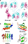
Targeting molecules. a IgG and its small fragments, b small molecular-binding scaffolds
Fig. 3
Fig. 3
Protein transduction using the streptavidin based nano-carrier. a Schematic illustration of protein transduction using the streptavidin based nano-carrier. b (1) Effect of the conjugation ratio of R15 peptides to SA on the fluorescence intensity of HeLa cells after uptake of AF546-labeled SA–R15 complex. (2) Effects of the length of Rpep on the fluorescence intensity of HeLa cells after uptake of AF546-labeled Rpep itself ant SA–Rpep complex (Figure reproduced with permission from: Ref. [61]. Copyright (2015) with permission from Elsevier)
Fig. 4
Fig. 4
Schematic illustration of photolytic P-Aggs formation and light-induced release of active proteins. a The chemical structure of BCR 1 consisting of a biotinylated photo-cleavable protection group (red) and an amino-reactive group (black). b Schemes of P-Aggs formation. c Protein photoliberation from P-Aggs (Figure reproduced with permission from: Ref. [62]. Copyright (2016) with permission from John Wiley and Sons)
Fig. 5
Fig. 5
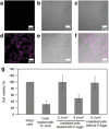
Light-induced cellular uptake of Tf or a chemotherapeutic drug through degradation of P-Aggs. ac Confocal microscopy images of DLD1 cells treated with P-Aggs consisting of SA and AF647-labeled caged Tf before light irradiation. df Those after light irradiation at 8 J cm−2. a, d AF647-fluorescence images, b, e differential interference contrast (DIC) images, c, f each merged image of (a, b) or (d, e), respectively. The scale bars are 50 μm. g Cell viabilities of the DLD1 cells treated with doxorubicin-modified Tf (Tf-DOX) or with P-Aggs consisting of SA and the caged Tf-DOX before and after light irradiation at 8 J cm−2 (Figure reproduced with permission from: Ref. [62]. Copyright (2016) with permission from John Wiley and Sons)
Fig. 6
Fig. 6
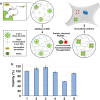
Peptide tag-induced HRP-mediated preparation of a streptavidin-immobilized redox-sensitive hydrogel. a Schematic illustration of HRP-mediated preparation of a streptavidin-immobilized redox-sensitive hydrogel and intracellular delivery. b Cytotoxicity assay of DLD1 cells incubated with C-SA-Y nanogel functionalized with CPP and saporin. The viability of cells without any treatment was set as 100%. Cells without any treatment (1) and treated with C-SA-Y nanogel (2), C-SA-Y nanogel with CPP (3), C-SA-Y nanogel with saporin (4), C-SA-Y nanogel with CPP and saporin (5), and saporin (6) (Figure reproduced with permission from Ref. [63]. Copyright (2016) with permission from American Chemical Society)
Fig. 7
Fig. 7
Design of microfluidic ECL array for cancer biomarker detection. (1) syringe pump, (2) injector valve, (3) switch valve to guide the sample to the desired channel, (4) tubing for inlet, (5) outlet, (6) poly(methylmethacrylate) plate, (7) Pt counter wire, (8) Ag/AgCl reference wire, (9) polydimethylsiloxane channels, (10) pyrolytic graphite chip (black), surrounded by hydrophobic polymer (white) to make microwells. Bottoms of microwells (red rectangles) contain primary antibody-decorated SWCNT forests, (11) ECL label containing RuBPY-silica nanoparticles with cognate secondary antibodies are injected to the capture protein analytes previously bound to cognate primary antibodies. ECL is detected with a CCD camera (Figure reproduced with permission from: Ref. [80]. Copyright (2013) with permission from Springer Nature)
Fig. 8
Fig. 8
Biofabrication for construction of nanodevices. Schematic of the procedure for orthogonal enzymatic assembly using tyrosinase to anchor the gelatin tether to chitosan and microbial transglutaminase to conjugate target proteins to the tether (Figure adapted with permission from: Ref. [83]. Copyright (2009) American Chemical Society)
Fig. 9
Fig. 9
Illustration of armored single-enzyme nanoparticle. a Schematic of preparation of the single-enzyme nanoparticles. b Chemistry for the synthesis of single-enzyme nanoparticles (Figure adapted with permission from Ref. [90]. Copyright (2003) American Chemical Society)
Fig. 10
Fig. 10
Illustration of different modes of organizing enzyme complexes. a Free enzymes, b metabolon (enzyme clusters), c fusion enzymes, d scaffolded enzymes
Fig. 11
Fig. 11
The branched fusion protein construction by MTGase-mediated site-specific protein conjugation. a A fusion protein of putidaredoxin reductase (PdR) and P450cam linked with a peptide containing a reactive Gln residue and putidaredoxin attached K-tag generated a three-way branched fusion protein by MTGase. b Reaction scheme for d-camphor hydroxylation by branched P450cam with cofactor regeneration in a reversed micellar system. c Effect of W0 on the initial activities of branched P450cam (open circles) and an equimolar mixture of PdR, PdX and P450cam (closed circles) (a adapted with permission from: Ref. [106]. Copyright (2012) Springer, b, c adapted with permission from Ref. [109]. Copyright (2010) Oxford University Press)
Fig. 12
Fig. 12
Schematic illustration of PCNA-mediated multienzyme complex formation. a Self-assembly of PCNA-based heterotrimeric complex (PUPPET) consisting of P450cam, its electron transfer-related proteins PdR and PdX that catalyzes the hydroxylation of d-camphor. b PTDH-PUPPET complex that catalyzes the hydroxylation of d-camphor by regenerating NADH with consumption of phosphite (a reproduced with permission from: Ref. [111]. Copyright (2010) Wiley–VCH. b Reproduced with permission from: Ref. [115]. Copyright (2013) Wiley–VCH)
Fig. 13
Fig. 13
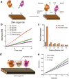
Schematic illustration of interenzyme substrate diffusion for an enzyme cascade organized on spatially addressable DNA nanostructures. a DNA nanostructure-directed coassembly of GOx and HRP enzymes with control over interenzyme distances and details of the GOx/HRP enzyme cascade. b Spacing distance-dependent effect of assembled GOx/HRP pairs as illustrated by plots of product concentration (Absorbance of ABTS) vs time for various nanostructured and free enzyme samples. c Enhancment of the activity of the enzyme pairs on DNA nanostructures compared to free enzyme in solution. d The design of an assembled GOx/HRP pair with a protein bridge used to connect the hydration surfaces of GOx and HRP. e Enhancement in the activity of assembled GOx/HRP pairs with β-Gal and NTV bridges compared to unbridged GOx/HRP pairs (Figure reproduced with permission from: Ref. [123]. Copyright (2012) American Chemical Society)
Fig. 14
Fig. 14
Overview of biomolecular engineering for enhancing, altering and multiplexing functions of biomolecules, and its application to various fields
Fig. 15
Fig. 15
The general procedure for the in vitro selection of aptamers or ribozymes
Fig. 16
Fig. 16
Illustrations of genetic recombination methods for protein evolution. a DNA shuffling (in vitro recombination of homologous genes). b ITCHY (in vitro recombination of homology-independent genes) (Figure adapted from Ref. [172])
Fig. 17
Fig. 17
Two general strategies and their procedures for protein engineering
Fig. 18
Fig. 18
Various genotype–phenotype linkage technologies. a Phage display technology. b Cell surface display technologies: in vivo display on the surface of bacteria, yeast or mammalian cell. c RNA display technology
Fig. 19
Fig. 19
Standard chemical conjugation technologies for proteins targeting at side chains of natural AA (Figure adapted with permission from: Ref. [213]. Copyright (2015) American Chemical Society)
Fig. 20
Fig. 20
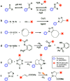
Chemoselective bioconjugation reactions. a Ketone/hydroxylamine condensations. b Copper-catalyzed alkyne–azide Huisgen cycloadditions. c Strain-promoted alkyne-azide cycloadditions. d Staudinger ligation. e Diels–Alder cycloadditions. f Photo-click cycloadditions (Figure adapted with permission from: Ref. [224]. Copyright (2014) American Chemical Society)
Fig. 21
Fig. 21
Native chemical ligation. Native chemical ligation (NCL) is a chemoselective coupling reaction that links a peptide fragment containing an N-terminal Cys (α-Cys) residue and another peptide fragment bearing a C-terminal α-thioester group by a native peptide bond (Figure reproduced with permission from: Ref. [106]. Copyright (2012) Springer)
Fig. 22
Fig. 22
Intein-based chemical conjugation. a Expressed protein ligation (EPL) is a semisynthetic version of NCL in which synthetic and recombinant polypeptides are chemically ligated together. Proteins (A) expressed as intein fusions can be cleaved from the intein with a variety of thiols to give the corresponding α-thioester derivative. Proteins (B) containing N-terminal Cys can be made recombinantly by masking the Cys with a protease tag that can be later removed. b Protein trans-splicing (PTS) post-translationally links two protein fragments. An intein domain is split into two fragments, IntN and IntC, which are fused to the flanking exteins, ExN and ExC. ExN–IntN and IntC–ExC associate and fold to form a functional intein. This functional intein can restore protein splicing activity to excise itself, and to conjugate ExN and ExC with a peptide bond (Figures adapted with permission from: Ref. [106]. Copyright (2012) Springer)
Fig. 23
Fig. 23
Chemoenzymatic labeling strategies of the protein of interest (POI) using post-translational modification enzymes. a Formylglycine generating enzyme (FGE) recognizes LCXPXR peptide motif and converts the side chain of Cys residue into an aldehyde group. The POI fused to the aldehyde tag can be further functionalized with aminooxy or hydrazide probes. b Farnesyltransferase (FTase) recognizes the four AAs sequence CA1A2X (A1 and A2 are non-charged aliphatic AAs and X is C-terminal Met, Ser or Phe) at the C-terminus and catalyzes the attachment of the farnesyl isoprenoid group to the Cys residue. The POI can be further labeled by bioorthogonal chemical conjugation of the farnesyl moiety functionalized with azide or alkyne. c N-Myristoyl transferase (NMT) recognizes the GXXXS peptide motif at the N-terminus and attaches a myristate group to an N-terminal Gly residue. The POI can be further labeled by bioorthogonal chemical conjugation of myristate moiety functionalized with azide or alkyne. d Biotin ligase recognizes the GGLNDIFEAQKIEWH peptide motif derived from biotin carboxyl carrier protein and catalyzes the transfer of biotin from an ATP intermediate (biotinyl 5′-adenylate) to Lys residue. Biotinylated POI can then be labeled with streptavidin conjugated with a variety of chemical probes. e Lipoic acid ligase recognizes the GFEIDKVWYDLDA peptide motif and catalyzes the attachment of lipoic acid or its derivatives to Lys residue in the motif. f Transglutaminase (TGase) catalyzes the transamination reaction and forms an iso-peptide bond between Gln in POI and Lys residue-functionalized small molecule probes, peptides or proteins. g Sortase cleaves LPXTG peptide tag fused to POI between Thr and Gly residue and conjugates oligo Gly-functionalized small molecule probes, peptides or proteins to POI by forming a peptide bond between Thr and Gly residues. h GST catalyzes Cys arylation and conjugates probes bearing a 4-mercaptoperfluorobiphenyl moiety to the N-terminal γ-Glu-Cys-Gly sequence of POI. i SpyLigase catalyzes the generation of an isopeptide bond between Lys residue in KTag and Asp residue in SpyTag
Fig. 24
Fig. 24
Self-labeling protein tags. a, b Both SNAP- and CLIP-tag derive from O 6-methylguanine-DNA methyltransferase with C145 as the active site. c The Halo-tag derives from haloalkane dehalogenase whose active site D106 forms an ester bond with the chloroalkane linker. d The TMP-tag noncovalently binds with trimethoprim and brings the α, β-unsaturated carbonyl (i) or sulfonyl (ii) into proximity of the engineered reactive Cys (L28C) (Figure adapted with permission from: Ref. [229]. Copyright (2017) American Chemical Society)
Fig. 25
Fig. 25
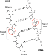
Schematic chemical structures of PNA and DNA. The circles show the different backbone linkages of PNA and DNA. A, T, G, and C denote adenine, thymine, guanine and cytosine, respectively
Fig. 26
Fig. 26
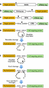
Schematic representation of the construction of self-cleaving fusion systems. Filled triangle indicates cleavage sites and X stands for any AA. a The construct of the original C-terminal intein fusion in which the target protein is fused to the N-terminus of the CBD-tagged intein. b The SrtA fusion construct that contains an N-terminal affinity-tag, SrtA catalytic core, the LPXTG motif and the target protein. Cleavage at the LPXTG site allows the release of the target protein with an extra N-terminal glycine. c The FrpC fusion construct that consists of the target protein and the affinity-tagged SPM. Cleavage at the Asp–Pro site (the first two AAs of SPM) results in the release of the target protein with an extra aspartate residue at its C-terminus. d The CPD fusion construct in which the affinity-tagged CPD is fused to the C-terminus of the target protein. The VD double residue in the linker sequence comes from the SalI restriction site used for cloning whereas ALADGK are residues contained within the CPD. e The dithiocyclopeptide linker with one protease-sensitive site. The fusion protein is linked via a dithiocyclopeptide linker containing a thrombin-specific sequence, PRS. The design of dithiocyclopeptide linker was based on the structure of the cyclopeptide, somatostatin, with the replacement of AA residues 8–10, WKT, by a thrombin-specific cleavage sequence, PRS. f The dithiocyclopeptide linker with three secretion signal processing protease-sensitive sites. The fusion protein is linked via a dithiocyclopeptide linker containing Kex1, Kex2 and Ste13-specific cleavage sequences. Kex2 cleaves RR↓E. Kex1 and Ste13 remove C-terminal RR and N-terminal EA, respectively
Fig. 27
Fig. 27
Optimization of the PCNA2-PdX fusion protein linker in PUPPET. a P450cam oxidation activities of the PUPPET linker variants, PUPPET-Pn (n = 1–5). b P450cam oxidation activities of the PUPPET linker variants, PUPPET-Gn (n = 1–6). c A docking model of P450cam and PdX. d Spatial arrangement of P450cam and the PCNA ring when the PdX-binding site of P450cam faces in the same direction to the PCNA ring. e Spatial arrangement of P450cam and the PCNA ring when the PdX-binding site of P450cam faces in a perpendicular direction to the PCNA ring (Figures reproduced from Ref. [343])
Fig. 28
Fig. 28
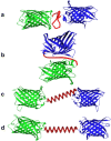
Schematic illustrations of various conformations of the fusion proteins. a EBFP (blue) and EGFP (green) are situated in a straight line, with the flexible linker (red) between the two domains. b EBFP and EGFP reside side by side, for the most compact conformation with the flexible linker. c The helical linker connects EBFP and EGFP diagonally. d The helical linker and the long axes of EBFP and EGFP are situated in a straight line (Figure adapted with permission from: Ref. [347]. Copyright (2004) John Wiley & Sons)
Fig. 29
Fig. 29
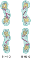
High-resolution models (cartoon representation) of the EBFP and EGFP connected with the helical linkers. B–H4–G and B–H5–G indicate EBFP–LA(EA3K)nAAA–EGFP (n = 4, 5), respectively. Low-resolution models based on only SAXS data are shown as wire-frames. The linker and the two domains are modeled and two different views are shown (Figure reproduced with permission from: Ref. [347]. Copyright (2004) John Wiley & Sons)

Similar articles

Cited by

References

    1. Chan WCW. Bionanotechnology progress and advances. Biol. Blood Marrow Transplant. 2006;12:87–91. doi: 10.1016/j.bbmt.2005.10.004. - DOI - PubMed
    1. Kovarik MK, Jacobson SC. Nanofluidics in lab-on-a-chip devices. Anal. Chem. 2009;81:7133–7140. doi: 10.1021/ac900614k. - DOI - PubMed
    1. West J, Becker M, Tombrink S, Manz A. Micro total analysis systems: latest achievements. Anal. Chem. 2008;80:4403–4419. doi: 10.1021/ac800680j. - DOI - PubMed
    1. Yager P, Edward T, Fu E, Helton K, Nelson K, Tam MR, Weigl BH. Microfluidic diagnostic technologies for global public health. Nature. 2006;442:412–418. doi: 10.1038/nature05064. - DOI - PubMed
    1. Chin CD, Linder V, Sia SK. Commercialization of microfluidic point-of-care diagnostic devices. Lab Chip. 2012;12:2118–2134. doi: 10.1039/c2lc21204h. - DOI - PubMed