Review
. 2017 Jun;8(3):319-328.
doi: 10.1007/s13244-017-0554-5. Epub 2017 May 12.

High-frame rate vector flow imaging of the carotid bifurcation

Affiliations
Review

High-frame rate vector flow imaging of the carotid bifurcation

Alfredo Goddi et al. Insights Imaging. 2017 Jun.

Abstract

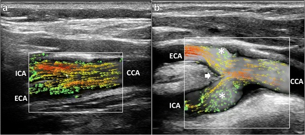
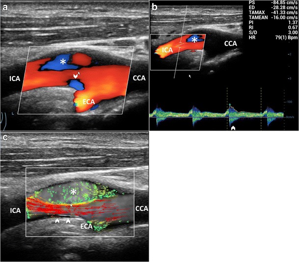
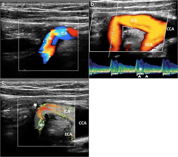
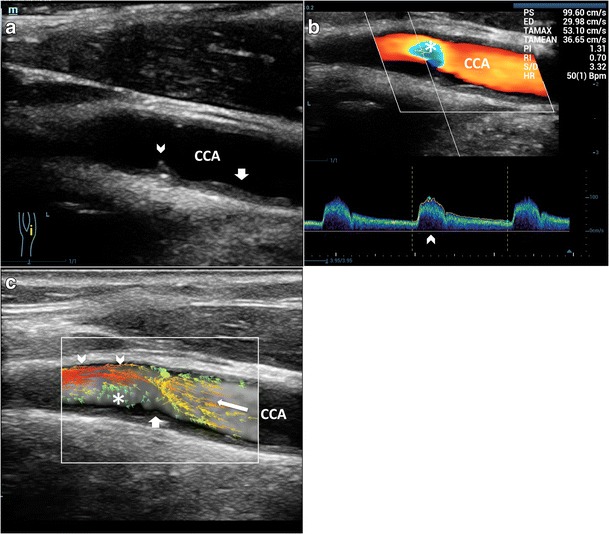
Carotid artery atherosclerotic disease is still a significant cause of cerebrovascular morbidity and mortality. A new angle-independent technique, measuring and visualizing blood flow velocities in all directions, called vector flow imaging (VFI) is becoming available from several vendors. VFI can provide more intuitive and quantitative imaging of vortex formation, which is not clearly distinguishable in the color Doppler image. VFI, as quantitative method assessing disturbed flow patterns of the carotid bifurcation, has the potential to allow better understanding of the diagnostic value of complex flow and to enhance risk stratification. This pictorial review article will show which new information VFI adds for the knowledge of hemodynamics in comparison to the conventional ultrasound techniques.

Teaching points: • VFI is an angle-independent technique measuring flow velocities in all directions. • This kind of VFI is based on a plane wave multidirectional excitation technique. • VFI allows quantitative assessment of carotid streamlines progression and visualizes vorticity. • VFI does not allow a precise comprehension of streamlines' 3D shape. • VFI allows a better understanding of carotid artery complex flows.

Keywords: Carotid arteries; Doppler; Plane wave imaging; Ultrasound; Vector flow imaging.


Figures

Fig. 1
Fig. 1
CD of the carotid bifurcation (CB). Complex flow is visible as a mosaic of colors (*), a mixture of velocities and directions; color assignment depends on the US beam direction. (a) Color-box steering of 20° to the left. (b) Color-box at 90°. CCA = Common carotid artery. ICA = Internal carotid artery. ECA = External carotid artery. STA = Superior thyroid artery
Fig. 2
Fig. 2
Multimodality Doppler evaluation of the CB. a) CD shows reverse flow in the sinus (**), at the ECA entrance (*); in the ICA complex flow (arrowhead), the behavior of which is not understandable due to angle dependence. b) PW at the ICA: bidirectional flow in the descending systole (arrowheads). c) VFI at the systolic peak. High-velocity red vectors near the flow divider in ICA (arrowhead) and ECA (white arrow). d) VFI in the descending systole. Multidirectional flow and vortexes (short green or yellow/orange vectors) in the ICA sinus (**) and at the ECA (*). CCA = Common carotid artery. ICA = Internal carotid artery. ECA = External carotid artery. STA = Superior thyroid artery
Fig. 3
Fig. 3
VFI of a straight CCA. Blood flows in thin parallel layers (red long vectors; *). The fluid near the boundary (orange/green vectors) moves at low velocity (arrowheads). CCA = Common carotid artery. JV = Jugular vein
Fig. 4
Fig. 4
Laminar flow assessment. a) CD and PW showing a flow pattern with parabolic profile (arrows) and minor spectral broadening (*), respectively. b) VFI at the peak systole shows the maximum velocity vectors. Low-velocity vectors (*) of the previous diastole. Maximum velocity point (void arrow). Yellow line (arrowhead): the moment the VFI frame was acquired. CCA = Common carotid artery
Fig. 5
Fig. 5
VFI patterns in CB various shapes. a) Tight angle between ICA and ECA: streamline laminar flow (red and orange vectors) during systole. b) Wide angle (> 45°) between ICA and ECA. The maximum velocity red vectors in the bulb hit the flow divider (short arrow), leading to the detachment of layers and generating vortex flow (*). CCA = Common carotid artery. ICA = Internal carotid artery. ECA = External carotid artery
Fig. 6
Fig. 6
Reverse flow in enlarged ICA sinus. a) CD shows reverse flow (*) along the opposite side to the divider and at their apex (arrowhead). b) PW: bidirectional flow (arrowhead), distally to the CD reverse flow (*), suggesting wider extension of vorticity. c) VFI outlines a high-velocity red vectors streamline (arrowheads) and a wide low flow vorticity (*). CCA = Common carotid artery. ICA = Internal carotid artery. ECA = External carotid artery
Fig. 7
Fig. 7
Flow assessment in kinked ICA (angle ≈90°). a) CD shows a mosaic of colors—aliasing artifact (*). b) Power Doppler outlines the lumen reduction (arrow), without any quantification. PW bidirectional flow (arrowhead) and spectral broadening (*) highlight the turbulence. c) VFI quantifies the stricture by showing high-velocity red vectors (short arrow) and strong vorticity (*). CCA = Common carotid artery. ICA = Internal carotid artery. ECA = External carotid artery
Fig. 8
Fig. 8
Flow patterns in low-degree stenosis. a) B-mode demonstrates atherosclerotic thickness (short arrows) and a rose thorn minor plaque (arrowhead). b) CD shows a limited area of increased velocity (*). PW excludes a relevant PSV (99 cm/s) and spectral broadening (arrowhead). c) VFI shows aminar flow before the plaque (arrow), layers detachment from the boundary (short arrow), eccentric max velocity vectors (arrowhead) and large complex flow (*) along the opposite wall. CCA = Common carotid artery
Fig. 9
Fig. 9
Flow vorticity in low-degree stenosis and vessel dilatation. a) B-mode depicts a rose thorn plaque (arrowhead) before an enlarged bulb (*); CD shows a mixture of velocities and directions. b) VFI quantifies a large vortex (short green vectors) (*) during systolic deceleration (arrowhead). High-velocity vectors streamline toward the posterior wall (black arrow). CCA = Common carotid artery. ICA = Internal carotid artery. JV = Jugular vein
Fig. 10
Fig. 10
Flow patterns in low-degree to moderate stenosis. a) B-mode and CD of the CB show a plaque (arrowhead) and increased velocities in the ICA (short arrow), respectively. PW measures a moderate velocity and spectral broadening (*). b) VFI at low PRF, at the peak systole (arrowhead) shows high-velocity red vectors. Long red vectors due to aliasing (arrow), start at the blue dot (void arrow), move back. Vector velocity (white arrow) is higher than the measured PW. c) At high PRF, VFI displays the higher velocities at the stenosis level (orange/yellow vectors). Reverse red vectors (arrow) start from the blue dot (void arrow). In b), c) recirculation depicted by green vectors (*). CCA = Common carotid artery. ICA = Internal carotid artery. ECA = External carotid artery
Fig. 11
Fig. 11
Flow patterns in moderate stenosis. a) B-mode and CD of the CB show an eccentric plaque (arrowhead; 50%–60% diameter stenosis) and increased velocities (white arrow). PW depicts an increased velocity (PSV 120 cm/s) and spectral broadening (*). b) Distally to the stenosis (arrow), CD shows a mixture of colors (*) due to aliasing and to the non-linear vessel course (curved arrows). c) VFI during systole: high-velocity vectors (*) at the stenosis; orange/yellow medium velocity vectors (arrowheads) and complex flow below: low-velocity green vectors and reverse flow red vectors (white short arrow). Turbulence duration (arrow). CCA = Common carotid artery. ICA = Internal carotid artery. ECA = External carotid artery
Fig. 12
Fig. 12
Flow patterns in hemodynamically relevant stenosis. a) B-mode and CD of the ICA sinus demonstrates a short plaque (arrowheads) causing severe stenosis: CD depicts a mixture of high velocities and directions (*), distally to the stenosis. b) VFI shows high-velocity vectors bundled (arrowheads) while entering the stenosis. Distally, turbulent flow coded by green/orange vectors, randomly oriented, and by reversed red vectors (short white arrow). Blue dot (void arrow): max velocity point. CCA = Common carotid artery. ICA = Internal carotid artery

Similar articles

Cited by

References

    1. Shields RC. Medical Management of Carotid Stenosis. Perspect Vasc Surg Endovasc Ther. 2010;22(1):18–27. doi: 10.1177/1531003510380929. - DOI - PubMed
    1. Ross R. The pathogenesis of atherosclerosis: a perspective for the 1990s. Nature. 1993;362:801–809. doi: 10.1038/362801a0. - DOI - PubMed
    1. Cecchia E, Giglioli C, Valentea S, et al. Role of hemodynamic shear stress in cardiovascular disease. Atherosclerosis. 2011;214:249–256. doi: 10.1016/j.atherosclerosis.2010.09.008. - DOI - PubMed
    1. Younis HF, Kaazempur-Mofrad MR, Chan RC, et al. Hemodynamics and wall mechanics in human carotid bifurcation and its consequences for atherogenesis: investigation of inter-individual variation. Biomech Model Mechanobiol. 2004;3:17–32. doi: 10.1007/s10237-004-0046-7. - DOI - PubMed
    1. Zarins CK, Giddens DP, Bharadvaj BK, et al. Carotid bifurcation atherosclerosis. Quantitative correlation of plaque localization with flow velocity profiles and wall shear stress. Circ Res. 1983;53:502–514. doi: 10.1161/01.RES.53.4.502. - DOI - PubMed

LinkOut - more resources