. 2017 May 3;11(3):034103.
doi: 10.1063/1.4983148. eCollection 2017 May.

Reconfigurable microfluidic device with discretized sidewall

Affiliations

Reconfigurable microfluidic device with discretized sidewall

Masahiro Oono et al. Biomicrofluidics. .

Abstract

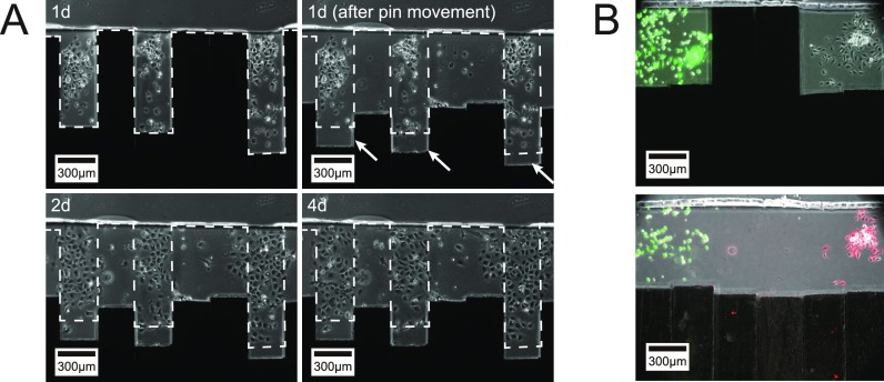
Various microfluidic features, such as traps, have been used to manipulate flows, cells, and other particles within microfluidic systems. However, these features often become undesirable in subsequent steps requiring different fluidic configurations. To meet the changing needs of various microfluidic configurations, we developed a reconfigurable microfluidic channel with movable sidewalls using mechanically discretized sidewalls of laterally aligned rectangular pins. The user can deform the channel sidewall at any time after fabrication by sliding the pins. We confirmed that the flow resistance of the straight microchannel could be reversibly adjusted in the range of 101-105 Pa s/μl by manually displacing one of the pins comprising the microchannel sidewall. The reconfigurable microchannel also made it possible to manipulate flows and cells by creating a segmented patterned culture of COS-7 cells and a coculture of human umbilical vein endothelial cells (HUVECs) and human lung fibroblasts (hLFs) inside the microchannel. The reconfigurable microfluidic device successfully maintained a culture of COS-7 cells in a log phase throughout the entire period of 216 h. Furthermore, we performed a migration assay of cocultured HUVEC and hLF spheroids within one microchannel and observed their migration toward each other.


Figures

FIG. 1.
FIG. 1.
Discretization of a microfluidic channel sidewall. (a) Typical microchannel with a ceiling and two vertical sidewalls. (b) Reconfigurable microchannel feature comprising an elastomeric half-channel and small machine elements, referred to as “pins”. One sidewall in (a) has been replaced with the packed end faces of lined machine elements. Each pin can move longitudinally, guided by adjacent pins.
FIG. 2.
FIG. 2.
Reconfigurable microfluidic channel with a discretized sidewall. (a) Top view of a microfluidic device with a reconfigurable microchannel, comprising a microfluidic channel with one straight fixed sidewall and a reservoir at each end. The device has typical soft lithography microfluidic features, such as a glass bottom and a poly(dimethylsiloxane) (PDMS) channel, but has one sidewall formed by the ends of ten stainless steel pins. The paraffin wax-based filler prevented liquid in the channel from leaking through the pin gaps, and a silicone adhesive barrier prevented filler leakage. An air vent channel was placed between the microchannel and the barrier edge to prevent shear flow around the moving pins from entering the microchannel. (b) Assembly process for the microfluidic device shown in (a): (1) dispensing paraffin wax-based filler and silicone elastomer on a glass substrate with a robotic dispenser; (2) bonding the PDMS channel with reservoirs to a glass slab. Rectangular pins are inserted in the gap between glass and PDMS, and the PDMS-pins-glass assembly is bonded to the substrate; and (3) dispensing more silicone elastomers and fillers to fully embed the middle of the pins.
FIG. 3.
FIG. 3.
Microchannel reconfiguration for in-channel cell manipulation. (a) Patterning one type of cell into multiple segments in a straight microchannel: (1) cells are seeded to a straight microfluidic channel; (2) pins are displaced to obstruct the channel; and (3) pins are returned to the straight position after cell adhesion. (b) Patterning two types of cells (human lung fibroblasts, hLFs, and HUVECs) into two segmented regions: (1) hLFs are introduced to the channel and obstructed by a “wall” using pin displacement; (2) the culture area of hLFs is defined by closing the pin upstream. HUVECs are then introduced at the opposite end of the channel and also obstructed by the wall; (3) excess HUVECs are driven from the channel; the culture area for HUVECs is defined; (4) the channels are returned to the straight position after adhesion of both cell types is observed. (c) Gradual cell culture area expansion in a reconfigurable microchannel. (1) Cells are seeded to a microfluidic channel. (2) Cells (between one and five) are confined within a space equal to one pin-width, and cells outside are aspirated. (3) After proliferation of the confined cells, the confined space is expanded. (4) Cell culture is kept nonconfluent by continuing to expand the culture area. (d) Spheroid coculture in a reconfigurable microchannel. (1) A HUVEC spheroid is introduced into the channel after narrowing the region near the outlet. (2) The spheroid settles before the narrow region, and another pin is moved to narrow the channel on the other side of the spheroid. (3) An hLF spheroid is introduced and settles before the pin actuated in step (2). (4) Another pin is moved to enclose both the settled HUVEC and LF spheroids between narrow regions, giving a coculture.
FIG. 4.
FIG. 4.
Flow resistance of a reconfigurable microchannel with the channel segment width varied by displacing one pin. A 300-μm-long region of the 3-mm-long channel was narrowed relative to the remaining channel (set width of 400 μm) by displacing one pin. As the width narrowed, flow resistance increased in inverse proportion to the cube of the width. Measurements were performed three times under each condition and are presented as mean ± SD.
FIG. 5.
FIG. 5.
Cell patterning in a reconfigurable microchannel with a movable discretized sidewall. (a) COS-7 cells patterned in a microchannel. The cells had adhered after 1 day, at which point all pins were retracted to open the channel. Pins that had already been retracted before 1 day were further retracted to examine the extent of cell migration into previously obstructed areas (indicated by white arrows). (b) Patterned coculture of human umbilical vein endothelial cells (HUVECs) and human lung fibroblasts (hLFs) in a reconfigurable microchannel. hLFs were stained with calcein AM (green fluorescent dye that stains live cells) before introducing into the microchannel, while a rhodamine-labeled lectin (red fluorescent dye that binds only to HUVECs) was added into the channels after both hLFs and HUVECs had been seeded.
FIG. 6.
FIG. 6.
Progressive and continuous cell growth with variable cell culture areas in a reconfigurable microchannel. (a) COS-7 cell growth in a cell culture area confined by moving sidewalls. On the seeding day (0 day), only two cells were present in the microfluidic channel. Pins were actuated to form a small culture area confining the cells. The cell culture area was gradually expanded by moving the pins at 2, 6, and 7 days. (b) Growth curve and time evolution of the density of COS-7 cells confined in variable-size culture areas in the reconfigurable microchannels shown in (a). A growth curve of COS-7 cells cultured on immediately open microchannels is shown as a dotted line fitted to measured average cell counts (N = 3, mean ± SD). Three vertical arrows denote the expansion of the cell culture area at 2, 6, and 7 days, respectively. In addition to cell count, cell densities are shown for the same culture areas, fitted individually with each exponential growth curve and used to estimate the local doubling time (td [h]) shown in the frames.
FIG. 7.
FIG. 7.
Migration assay of cocultured single spheroids spaced in a reconfigurable microchannel. (a) Static coculture of HUVEC (left) and hLF (right) spheroids in a reconfigurable microchannel for 5 days. At 0 day, each spheroid was introduced to a different cultivation area. The cultivation areas were connected by a narrow channel segment defined by a pin that also acted as a wall. (b) HUVEC (left) and hLF (right) spheroids cocultured for 5 days on a vibrating table placed on a CO2 incubator. (c) Migration vectors of spheroids presented as polar plots of data obtained in (a) and (b). The zero degree was defined by the direction from a spheroid to the middle point of the segmented channels (shown in (a)). Data are representative of three similar experiments.

Similar articles

Cited by

References

    1. Montanez-Sauri S. I., Beebe D. J., and Sung K. E., Cell Mol. Life Sci. 72(2), 237–249 (2015).10.1007/s00018-014-1738-5 - DOI - PMC - PubMed
    1. Schober A., Fernekorn U., Singh S., Schlingloff G., Gebinoga M., Hampl J., and Williamson A., Eng. Life Sci. 13(4), 352–367 (2013).10.1002/elsc.201200088 - DOI
    1. Hakanson M., Cukierman E., and Charnley M., Adv. Drug Delivery Rev. 69–70, 52–66 (2014).10.1016/j.addr.2013.11.010 - DOI - PMC - PubMed
    1. Abbott R. D. and Kaplan D. L., Trends Biotechnol. 33(7), 401–407 (2015).10.1016/j.tibtech.2015.04.003 - DOI - PMC - PubMed
    1. Temiz Y., Lovchik R. D., Kaigala G. V., and Delamarche E., Microelectron. Eng. 132, 156–175 (2015).10.1016/j.mee.2014.10.013 - DOI

LinkOut - more resources