

Continuous variables logic via coupled automata using a DNAzyme cascade with feedback
- PMID: 28507669
- PMCID: PMC5407271
- DOI: 10.1039/c6sc03892a
Continuous variables logic via coupled automata using a DNAzyme cascade with feedback
Abstract
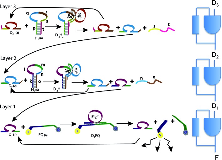
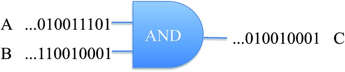
The concentration of molecules can be changed by chemical reactions and thereby offer a continuous readout. Yet computer architecture is cast in textbooks in terms of binary valued, Boolean variables. To enable reactive chemical systems to compute we show how, using the Cox interpretation of probability theory, one can transcribe the equations of chemical kinetics as a sequence of coupled logic gates operating on continuous variables. It is discussed how the distinct chemical identity of a molecule allows us to create a common language for chemical kinetics and Boolean logic. Specifically, the logic AND operation is shown to be equivalent to a bimolecular process. The logic XOR operation represents chemical processes that take place concurrently. The values of the rate constants enter the logic scheme as inputs. By designing a reaction scheme with a feedback we endow the logic gates with a built in memory because their output then depends on the input and also on the present state of the system. Technically such a logic machine is an automaton. We report an experimental realization of three such coupled automata using a DNAzyme multilayer signaling cascade. A simple model verifies analytically that our experimental scheme provides an integrator generating a power series that is third order in time. The model identifies two parameters that govern the kinetics and shows how the initial concentrations of the substrates are the coefficients in the power series.
Figures
Similar articles
-
Complete all-optical processing polarization-based binary logic gates and optical processors.Opt Express. 2006 Oct 16;14(21):9879-95. doi: 10.1364/oe.14.009879. Opt Express. 2006. PMID: 19529381
-
Logic reversibility and thermodynamic irreversibility demonstrated by DNAzyme-based Toffoli and Fredkin logic gates.Proc Natl Acad Sci U S A. 2012 Dec 26;109(52):21228-33. doi: 10.1073/pnas.1219672110. Epub 2012 Dec 12. Proc Natl Acad Sci U S A. 2012. PMID: 23236131 Free PMC article.
-
Light sensitive Belousov-Zhabotinsky medium accommodates multiple logic gates.Biosystems. 2021 Aug;206:104447. doi: 10.1016/j.biosystems.2021.104447. Epub 2021 May 24. Biosystems. 2021. PMID: 34033907
-
Boolean Logic Gates Realized with Enzyme-catalyzed Reactions - Unusual Look at Usual Chemical Reactions.Chemphyschem. 2019 Jan 7;20(1):9-22. doi: 10.1002/cphc.201800900. Epub 2018 Nov 20. Chemphyschem. 2019. PMID: 30358034 Review.
-
Biosensors with built-in biomolecular logic gates for practical applications.Biosensors (Basel). 2014 Aug 27;4(3):273-300. doi: 10.3390/bios4030273. eCollection 2014 Sep. Biosensors (Basel). 2014. PMID: 25587423 Free PMC article. Review.
Cited by
-
Propelling DNA Computing with Materials' Power: Recent Advancements in Innovative DNA Logic Computing Systems and Smart Bio-Applications.Adv Sci (Weinh). 2020 Nov 9;7(24):2001766. doi: 10.1002/advs.202001766. eCollection 2020 Dec. Adv Sci (Weinh). 2020. PMID: 33344121 Free PMC article. Review.
-
A label-free and enzyme-free platform with a visible output for constructing versatile logic gates using caged G-quadruplex as the signal transducer.Chem Sci. 2017 Oct 20;9(2):300-306. doi: 10.1039/c7sc04007e. eCollection 2018 Jan 14. Chem Sci. 2017. PMID: 29629099 Free PMC article.
-
DNA-based visual majority logic gate with one-vote veto function.Chem Sci. 2015 Mar 1;6(3):1973-1978. doi: 10.1039/c4sc03495c. Epub 2015 Jan 7. Chem Sci. 2015. PMID: 28706647 Free PMC article.
-
A Novel Fluorescent Aptamer Sensor with DNAzyme Signal Amplification for the Detection of CEA in Blood.Sensors (Basel). 2023 Jan 24;23(3):1317. doi: 10.3390/s23031317. Sensors (Basel). 2023. PMID: 36772357 Free PMC article.
-
Contrary logic pairs and circuits using a visually and colorimetrically detectable redox system consisting of MoO3-x nanodots and 3,3'-diaminobenzidine.Mikrochim Acta. 2019 Jan 9;186(2):79. doi: 10.1007/s00604-018-3190-y. Mikrochim Acta. 2019. PMID: 30627952
References
-
- Kohavi Z. and Jha N. K., Switching and finite automata theory, Cambridge University Press, Cambridge, 2010.
-
- Mano M. M. R., Kime C. R. and Martin T., Logic and Computer Design Fundamentals, Pearson Education, Upper Saddle River, NJ, 2016.
-
- Andreasson J., Pischel U. Chem. Soc. Rev. 2015;44:1053–1069. - PubMed
-
- de Ruiter G., van der Boom M. E. Acc. Chem. Res. 2011;44:563–573. - PubMed
-
- deSilva A. P., Molecular Logic-based Computation, RSC, Cambridge, 2012.
LinkOut - more resources
Full Text Sources
Other Literature Sources
Miscellaneous