

The Failure Envelope Concept Applied To The Bone-Dental Implant System
- PMID: 28515495
- PMCID: PMC5435678
- DOI: 10.1038/s41598-017-02282-2
The Failure Envelope Concept Applied To The Bone-Dental Implant System
Abstract
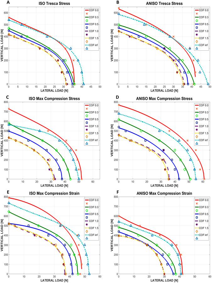
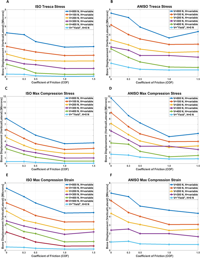
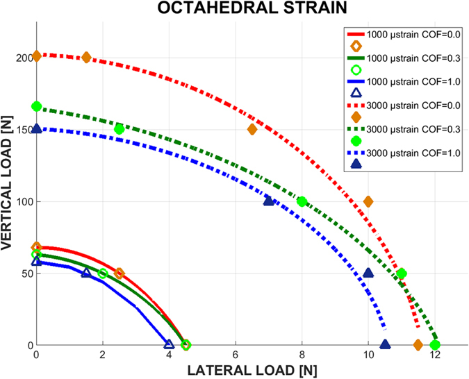
Dental implants interact with the jawbone through their common interface. While the implant is an inert structure, the jawbone is a living one that reacts to mechanical stimuli. Setting aside mechanical failure considerations of the implant, the bone is the main component to be addressed. With most failure criteria being expressed in terms of stress or strain values, their fulfillment can mean structural flow or fracture. However, in addition to those effects, the bony structure is likely to react biologically to the applied loads by dissolution or remodeling, so that additional (strain-based) criteria must be taken into account. While the literature abounds in studies of particular loading configurations, e.g. angle and value of the applied load to the implant, a general study of the admissible implant loads is still missing. This paper introduces the concept of failure envelopes for the dental implant-jawbone system, thereby defining admissible combinations of vertical and lateral loads for various failure criteria of the jawbone. Those envelopes are compared in terms of conservatism, thereby providing a systematic comparison of the various failure criteria and their determination of the admissible loads.
Conflict of interest statement
The authors declare that they have no competing interests.
Figures
Similar articles
-
Effects of implant diameter, insertion depth, and loading angle on stress/strain fields in implant/jawbone systems: finite element analysis.Int J Oral Maxillofac Implants. 2009 Sep-Oct;24(5):877-86. Int J Oral Maxillofac Implants. 2009. PMID: 19865628
-
On stress/strain shielding and the material stiffness paradigm for dental implants.Clin Implant Dent Relat Res. 2017 Oct;19(5):935-943. doi: 10.1111/cid.12509. Epub 2017 Jun 13. Clin Implant Dent Relat Res. 2017. PMID: 28608498
-
Biomechanical investigations of the expanded platform-switching concept in immediately loaded small diameter implants.J Prosthet Dent. 2016 Jan;115(1):20-5. doi: 10.1016/j.prosdent.2015.08.005. Epub 2015 Sep 28. J Prosthet Dent. 2016. PMID: 26421604
-
The effects of age, jaw site, and bone condition on oral implant outcomes.Int J Prosthodont. 1998 Sep-Oct;11(5):470-90. Int J Prosthodont. 1998. PMID: 9922739 Review.
-
Immediate loading in partially and completely edentulous jaws: a review of the literature with clinical guidelines.Periodontol 2000. 2014 Oct;66(1):153-87. doi: 10.1111/prd.12040. Periodontol 2000. 2014. PMID: 25123767 Review.
Cited by
-
Modeling the debonding process of osseointegrated implants due to coupled adhesion and friction.Biomech Model Mechanobiol. 2023 Feb;22(1):133-158. doi: 10.1007/s10237-022-01637-7. Epub 2022 Oct 25. Biomech Model Mechanobiol. 2023. PMID: 36284076 Free PMC article.
-
The Effect of Three-Dimensional Stabilization Thread Design on Biomechanical Fixation and Osseointegration in Type IV Bone.Biomimetics (Basel). 2025 Jun 12;10(6):395. doi: 10.3390/biomimetics10060395. Biomimetics (Basel). 2025. PMID: 40558364 Free PMC article.
-
Biomechanical behaviours of the bone-implant interface: a review.J R Soc Interface. 2019 Jul 26;16(156):20190259. doi: 10.1098/rsif.2019.0259. Epub 2019 Jul 31. J R Soc Interface. 2019. PMID: 31362615 Free PMC article. Review.
-
Beneficial osseointegration effect of hydroxyapatite coating on cranial implant - FEM investigation.PLoS One. 2021 Jul 19;16(7):e0254837. doi: 10.1371/journal.pone.0254837. eCollection 2021. PLoS One. 2021. PMID: 34280226 Free PMC article.
-
Strain-rate-dependent plasticity of Ta-Cu nanocomposites for therapeutic implants.Sci Rep. 2023 Sep 22;13(1):15788. doi: 10.1038/s41598-023-43126-6. Sci Rep. 2023. PMID: 37737499 Free PMC article.
References
-
- Timoshenko S. Strength of Materials. Strength Mater. 1976;2:510.
-
- Frost HM. A 2003 update of bone physiology and Wolff s law for clinicians. Angle Orthodontist. 2004;74:3–15. - PubMed
MeSH terms
Substances
LinkOut - more resources
Full Text Sources
