Review
. 2017 Jun 5;149(6):613-622.
doi: 10.1085/jgp.201611740. Epub 2017 May 18.

Interpreting the functional role of a novel interaction motif in prokaryotic sodium channels

Affiliations
Review

Interpreting the functional role of a novel interaction motif in prokaryotic sodium channels

Altin Sula et al. J Gen Physiol. .

Abstract

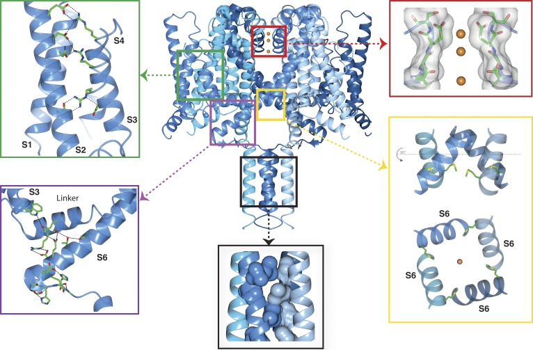
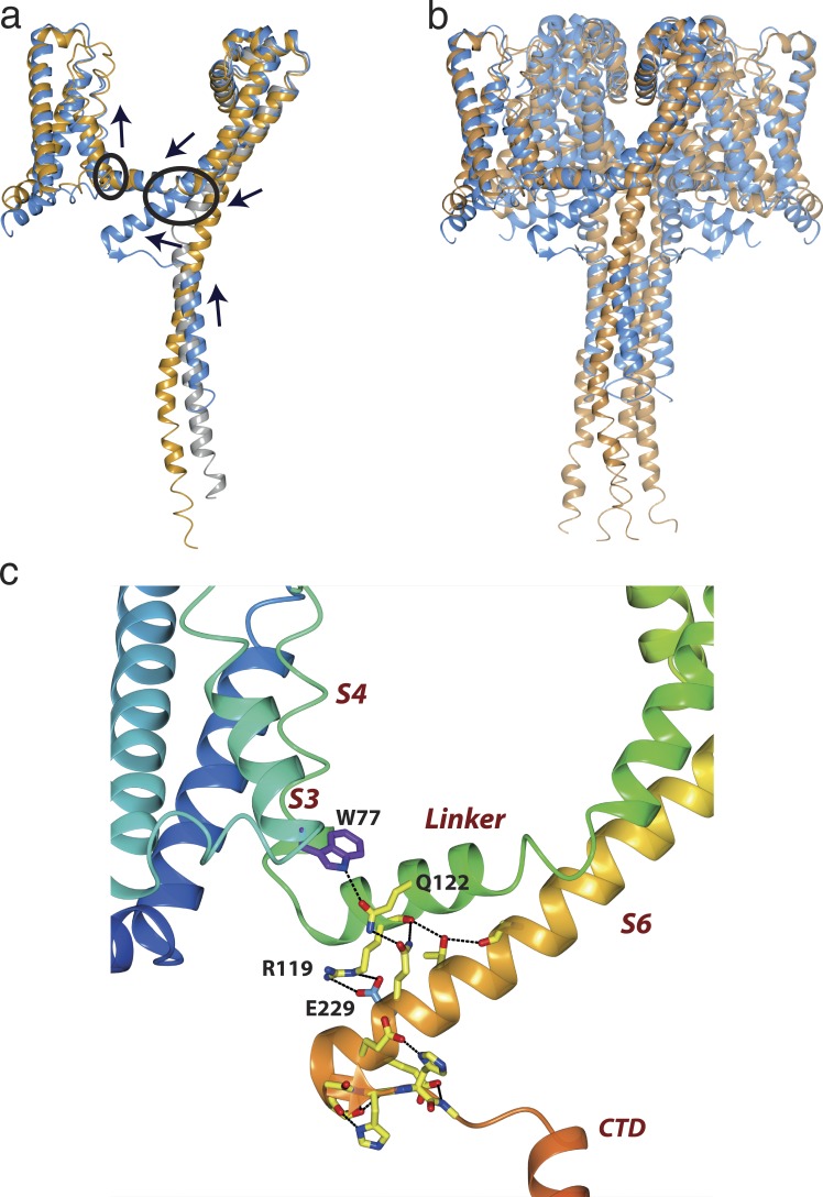
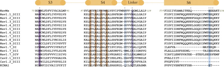
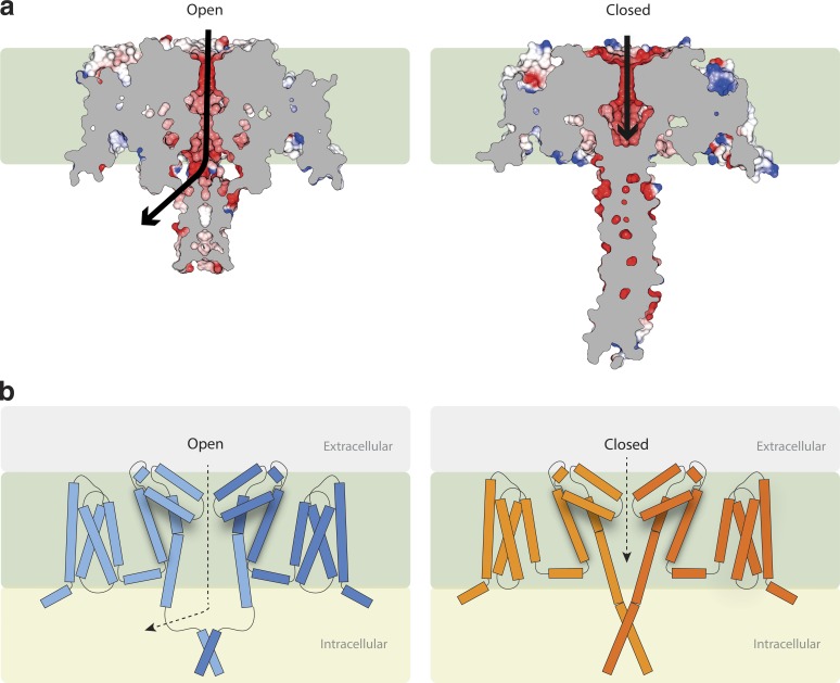
Voltage-gated sodium channels enable the translocation of sodium ions across cell membranes and play crucial roles in electrical signaling by initiating the action potential. In humans, mutations in sodium channels give rise to several neurological and cardiovascular diseases, and hence they are targets for pharmaceutical drug developments. Prokaryotic sodium channel crystal structures have provided detailed views of sodium channels, which by homology have suggested potentially important functionally related structural features in human sodium channels. A new crystal structure of a full-length prokaryotic channel, NavMs, in a conformation we proposed to represent the open, activated state, has revealed a novel interaction motif associated with channel opening. This motif is associated with disease when mutated in human sodium channels and plays an important and dynamic role in our new model for channel activation.


Figures

Figure 1.
Figure 1.
Functional regions of the open activated full-length NavMs sodium channel. The four monomers of PDB ID 5HVX are depicted in ribbon motif in different shades of blue. The boxed regions point to expanded views of the VS, SF, pore gate, CTD, and IM. Top left (green box) inset: VS helices, showing the side chains of the canonical arginines of the S4 helix (indicated in the Fig. 4 sequence figure) and their partners in helices S1, S2, and S3. These are the ion pairings expected for an activated (“outwardly facing”) VS. The α-helical transmembrane helices are in cartoon ribbon depictions, whereas the top of the S4 helix, which is a 310 helix, is in worm depiction. The latter feature is consistent with the proposal that the transition from inactivated (fully α-helical) to activated states (310/α-helical) would involve changes in the helical parameters, as well as the arginine bonding partners (Villalba-Galea et al., 2008). Top right (red box) inset: The SF, with backbone and side chain atoms (only two subunits shown), is depicted as sticks overlaid in surface display mode; the three sodium ions are orange balls (radius not to scale, for ease of visualization). The closest residue to any of the ions is E178, which is adjacent to the top sodium ion, as previously seen in the NavMs pore structure (Naylor et al., 2016). All of the ion–polypeptide distances are too long to involve direct contacts and so must be via (mostly disordered) water molecules. Bottom right (yellow box) inset: (top) The open pore gate in S6 is depicted in ribbon mode with the side chains shown in stick mode for the Met222 residues, which correspond to the region previously identified as the closed channel gate constriction. The bottom panel is a 90° rotation view showing the end-on-view of the pore gate, again with the Met222 side chains shown. Bottom middle (black box) inset: The coiled-coil region of the CTD, with the hydrophobic side chains forming the knob-into-holes motif, shown in space-filling depiction (for clarity only the side chains from two of the helices are shown). Bottom left (purple box) inset: The IM showing the extensive network of hydrogen bonds and ion pairings (dashed black lines) involving both side chains and peptide backbone moieties. The S3, S4–S5 linker, and S6 helices are depicted in ribbon motif. The residues involved in the hydrogen-bonded network are shown as sticks in CPK coloring. This and the other graphics figures were created using CCP4Mg (McNicholas et al., 2011) software.
Figure 2.
Figure 2.
Internal pore dimensions of open and closed transmembrane domains. (a) The open NavMs (in blue ribbon depiction). (b) The closed CavAb (in orange ribbon depiction). The inner surface dimensions as calculated using HOLE (Smart et al., 1996) are shown in dark blue, where the dimensions are sufficient to enable passage of fully hydrated sodium ions, in green where the dimensions are compatible with at least partially dehydrated ions, and red where the dimensions are too narrow to allow passage of sodium ions. Throughout the length of the pore from the extramembranous vestibule area, through the SF, into the bulbous hydrophobic cavity, which binds channel blocker compounds, until ∼14 Å from the intracellular surface, both open and closed structures are very similar and can accommodate sodium ions. However, near the exit of the pore, the closed pore narrows substantially, whereas the open pore retains a clear passage for the ions to exit the transmembrane region of the channel.
Figure 3.
Figure 3.
Features of open and closed sodium channels. (a) Overlays of the NavMs (blue), CavAb (orange), and NavAe1 (gray) monomer structures, with black arrows indicating the relative directions of the concerted movements of the VS, S4–S5 linker, S6 pore helix, IM, and top of the CTD when transforming from the open to the closed conformation. (b) Overlays of the complete NavMs (blue) and CavAb (orange) tetrameric structures, showing the overall consequences of the open-to-closed conformational change. The extensions of the S6 helices in NavMs splay the “neck” region of the CTD in the direction of the S4–S5 linker, which then results in a bend angle of nearly 120° at the beginning of the region without canonical secondary structure. This region has been designated the IM of the open state. In the closed CavAb structure, the equivalent “neck” region at the top of the CTD is a helical extension of the narrower opening formed by its S6 helices. As a consequence of the different conformations at the tops of their CTDs, the distal ends of the CavAb CTD (formed of coiled-coils in both structures) protrude into the cytoplasm, further from the membrane interface than they do in NavMs. (c) Enlarged view of the NavMs IM, with the helices depicted in rainbow colored (N- to C-terminal direction) ribbon motif. The regions (S3, S4–S5 linker, S6, and CTD) comprising the IM are labeled in red italics. The side chain and backbone atoms that are involved in the extensive network of hydrogen bonds and ion pairs (dashed lines) are shown in stick motif. The conserved W77 is in purple, and E229 is in cyan.
Figure 4.
Figure 4.
Alignments of sequences involved in the IM region. NavMs, domain III of all human Navs, all domains of the human Nav1.7 isoform, and other ion channels (calcium channels [one (Cav2.1) with, one (Cav1.2) without the conserved tryptophan], and the KCNA1 potassium channels) are listed. The locations of the helical regions in the NavMs structure are indicated by the orange bars at the top, and the numbers of the first and last residues of NavMs in each of the segments are noted in italics before/after each segment sequence. The residues of the IM where salt bridges/hydrogen bonds involving side chains are located are noted by the * above the sequence. The colored overlays indicate the conserved tryptophan in S3 (dark purple) and its partner residue (light purple), the E229 in S6 (cyan), and its partner R119 in the linker (light cyan), and for reference, the four VS arginines are in red.
Figure 5.
Figure 5.
Gating and ion translocation. (a) Lateral (transmembrane) slice through the centers of the NavMs (left) and CavAb (right) structures. Slabs through the space-filling models show the pathway (black arrows) for ion egress in the open NavMs structure via the opening at the side of the CTD adjacent to the end of the intramembrane pore region and the blockage at the end of the CavAb structure, ending before the end of the transmembrane pore region, which prevents ions exiting the pore. (In both parts a and b of this figure, the hydrophobic region of the membrane is represented by the green background.) (b) New model for channel gating (a modification to the earlier Bagnéris et al. [2013] and Shaya et al. [2014] models), now depicting schematically the role of the IM in stabilizing the open conformation formed by the splayed bottoms of the S6 helices. Left: The activated (open) state. Right: The resting (closed) state. For simplicity, only two subunits are shown for each structure. The tubes represent helical structures, and the connecting lines are segments that are not helical. The distal ends of the CTDs in both cases act to stabilize the tetrameric structures.

References

    1. Ahern C.A., Payandeh J., Bosmans F., and Chanda B.. 2016. The hitchhiker’s guide to the voltage-gated sodium channel galaxy. J. Gen. Physiol. 147:1–24. 10.1085/jgp.201511492 - DOI - PMC - PubMed
    1. Ahuja S., Mukund S., Deng L., Khakh K., Chang E., Ho H., Shriver S., Young C., Lin S., Johnson J.P. Jr., et al. . 2015. Structural basis of Nav1.7 inhibition by an isoform-selective small-molecule antagonist. Science. 350:aac5464 10.1126/science.aac5464 - DOI - PubMed
    1. Arrigoni C., Rohaim A., Shaya D., Findeisen F., Stein R.A., Nurva S.R., Mishra S., Mchaourab H.S., and Minor D.L. Jr. 2016. Unfolding of a temperature-sensitive domain controls voltage-gated channel activation. Cell. 164:922–936. 10.1016/j.cell.2016.02.001 - DOI - PMC - PubMed
    1. Bagnéris C., DeCaen P.G., Hall B.A., Naylor C.E., Clapham D.E., Kay C.W.M., and Wallace B.A.. 2013. Role of the C-terminal domain in the structure and function of tetrameric sodium channels. Nat. Commun. 4:2465 10.1038/ncomms3465 - DOI - PMC - PubMed
    1. Bagnéris C., DeCaen P.G., Naylor C.E., Pryde D.C., Nobeli I., Clapham D.E., and Wallace B.A.. 2014. Prokaryotic NavMs channel as a structural and functional model for eukaryotic sodium channel antagonism. Proc. Natl. Acad. Sci. USA. 111:8428–8433. 10.1073/pnas.1406855111 - DOI - PMC - PubMed

MeSH terms

Substances