. 2017 Jun 6;114(23):E4564-E4573.
doi: 10.1073/pnas.1620149114. Epub 2017 May 22.

Angular measurements of the dynein ring reveal a stepping mechanism dependent on a flexible stalk

Affiliations

Angular measurements of the dynein ring reveal a stepping mechanism dependent on a flexible stalk

Lisa G Lippert et al. Proc Natl Acad Sci U S A. .

Abstract

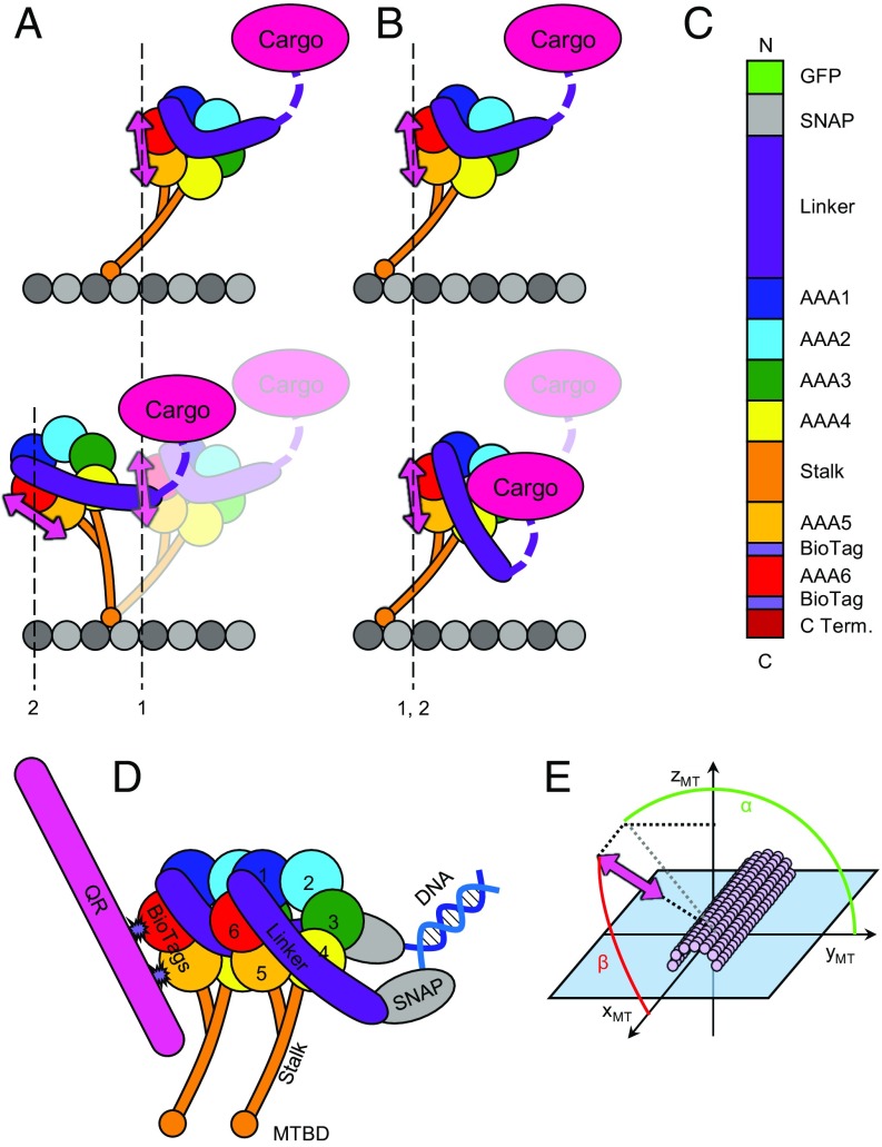
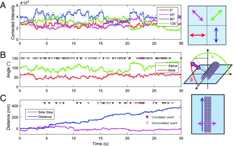
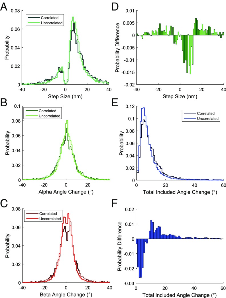
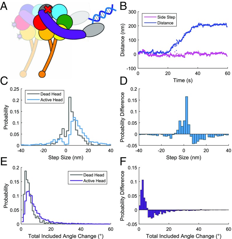
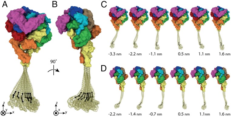
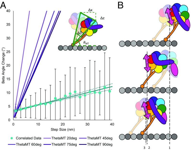
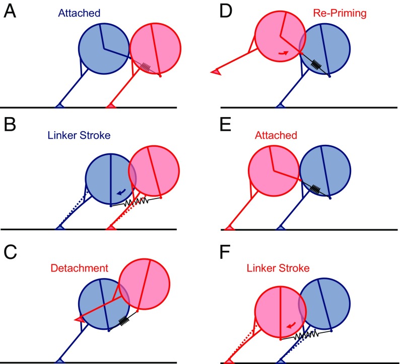
The force-generating mechanism of dynein differs from the force-generating mechanisms of other cytoskeletal motors. To examine the structural dynamics of dynein's stepping mechanism in real time, we used polarized total internal reflection fluorescence microscopy with nanometer accuracy localization to track the orientation and position of single motors. By measuring the polarized emission of individual quantum nanorods coupled to the dynein ring, we determined the angular position of the ring and found that it rotates relative to the microtubule (MT) while walking. Surprisingly, the observed rotations were small, averaging only 8.3°, and were only weakly correlated with steps. Measurements at two independent labeling positions on opposite sides of the ring showed similar small rotations. Our results are inconsistent with a classic power-stroke mechanism, and instead support a flexible stalk model in which interhead strain rotates the rings through bending and hinging of the stalk. Mechanical compliances of the stalk and hinge determined based on a 3.3-μs molecular dynamics simulation account for the degree of ring rotation observed experimentally. Together, these observations demonstrate that the stepping mechanism of dynein is fundamentally different from the stepping mechanisms of other well-studied MT motors, because it is characterized by constant small-scale fluctuations of a large but flexible structure fully consistent with the variable stepping pattern observed as dynein moves along the MT.

Keywords: TIRF; dynein; molecular dynamics; polarization; single molecule.


Conflict of interest statement

The authors declare no conflict of interest.

Figures

Fig. 1.
Fig. 1.
(A) Power-stroke stepping model. The ring and the stalk tilt with respect to the MT as a rigid lever arm, resulting in translocation of both the cargo and the motor domain from position 1 to position 2. In this model, the fluorescent probe used in this study (pink doubled-headed arrow) would translocate from position 1 (prepower stroke) to position 2 (postpower stroke) and undergo a rotation of the same magnitude as the ring and stalk. (B) Linker swing or winch stepping model. The ring and stalk maintain a relatively fixed orientation with respect to the MT. Translocation of the cargo is a result of linker (violet segment) straightening in a working stroke and docking to the ring. The probe undergoes little or no translocation or rotation during this conformational change. (C) Domain organization of the 331-kDa tail-truncated and doubly biotinylated dynein construct. Biotinylation target sequences (light purple, “BioTag”) are inserted in AAA5 and AAA6 of the ring domain. C Term., C terminus. (D) Schematic of the heterodimeric dynein construct. Dynein is dimerized via short cDNA oligonucleotides covalently attached to SNAP tags at the dynein N terminus. Heterodimeric constructs contain one doubly biotinylated head, as shown in C, and one wild-type head that lacks the BioTags. (E) Definition of probe orientation angles with respect to the MT frame of reference. The x axis points toward the direction of dynein motion (the minus end of the MT). The y axis is in the plane of the microscope slide. Angles are expressed in terms of α (green), the azimuthal angle of the probe around the MT, and β (red), the probe angle relative to the MT axis.
Fig. 2.
Fig. 2.
(A) Polarized fluorescence intensities measured at 0° (red), 45° (magenta), 90° (blue), and 135° (green) with respect to the microscope x axis and normalized for differential channel sensitivity. Dots represent the values measured in each camera frame, and bold lines are the same data averaged between identified state transitions or change points (Materials and Methods). (B) Probe angles α (green) and β (red) calculated from the intensities in A. Dots denote angles calculated from frame-by-frame intensities, whereas solid lines show the angles calculated from the intensities averaged between change points. (C) Distance traveled along the path of the MT (blue) or the sideways deviations from that path (side steps, magenta) by the same dynein motor shown in A and B. Dots show the positions of the dynein measured in each frame, and solid lines are the positions averaged between steps identified as change points. Triangles mark the times of detected angle changes (B) or steps along the MT path (C). Correlated steps and angle changes are marked with solid red triangles, whereas uncorrelated angle changes (B) and steps (C) are marked with open triangles. Data were collected at 100 μM MgATP.
Fig. 3.
Fig. 3.
Histograms of all step sizes and angle changes for all events measured at 100 μM ATP with QRs attached to AAA5 and AAA6 (Nmotors = 142). (A) Probability distribution of step sizes either correlated with an angle change (green) or not correlated with an angle change (uncorrelated, dark green). Histograms were normalized so that the total heights of all of the bars add up to 1.0. Probabilities are then calculated directly from histogram bar heights. A step change and angle change were considered correlated if they occurred within one frame (50 ms) of each other (Ncorrelated = 3,972, Nuncorrelated = 4,361). Probability distributions of α (B, green), β (C, red), or total included (E, blue) angle changes either correlated with a step (correlated, darker lines) or not correlated with a step (uncorrelated, lighter lines) are shown (Ncorrelated = 3,972, Nuncorrelated = 15,010). (D) Probability difference between the step size distributions plotted in A (correlated step probability minus uncorrelated step probability). (F) Probability difference between total included angle change distributions plotted in E (correlated angle change probability minus uncorrelated angle change probability).
Fig. 4.
Fig. 4.
Steps and angle changes of a “dead-head” heterodimeric construct measured at 100 μM MgATP on axonemes (Nmotors deadhead = 13, Nmotors WT = 38). (A) Schematic of the dynein heterodimer construct used in this experiment. One head contains a lysine-to-alanine mutation at residue 1,802, which renders it unable to bind ATP in AAA1, creating a dead head (denoted by a red x). The active head contains the two biotinylation sites as shown in Fig. 1C. The two heads are dimerized using cDNA oligonucleotides bound to their respective N-terminal SNAP tags. (B) Distance traveled along the path of an axoneme (blue) or sideways deviations from the path (side steps, magenta) by a single dynein motor tracked using QR fluorescence. Dots are the position measured in each camera frame, and solid lines are positions averaged between detected steps. (C) Probability distribution of step sizes of a QR-labeled heterodimer paired with either a dead-head mutant (gray) or an active wild-type head (blue) on axonemes (Ndeadsteps = 310, NWTsteps = 1,616). (D) Probability difference of the data plotted in C, dead-head construct steps minus active construct. (E) Probability distribution of total included angle changes of a QR-labeled heterodimer paired with either a dead-head mutant (gray) or an active wild-type head (purple) (Ndeadangles = 646, NWTangles = 3,107). (F) Probability difference of the data plotted in E, dead-head construct minus active head construct.
Fig. 5.
Fig. 5.
All-atom MD simulations of the dynein stalk demonstrate its flexibility along the coiled-coil region and at the MTBD hinge. An overlay of seven representative frames, each from the ensemble of 330,000 collected over 3.3 μs, selected to illustrate 99% of the structural distribution of stalk positions in the plane of the ring (A) and perpendicular to the plane of the ring (B) is shown. Distributions are determined with respect to alignment of the stalk to the heptad at its base (as described in Materials and Methods) and capture the distal tip of the stalk (hinge vertex) at its point closest to zero displacement and three equally spaced displacements out to ±2.5 SD in each plane. (C and D) Individual frames from A and B, with displacement of the distal tip of the stalk (hinge vertex) indicated in nanometers. Images were rendered using VMD 1.9.2 (64).
Fig. 6.
Fig. 6.
(A) Magnitudes of β-angle changes correlated with forward steps as a function of step size (teal points). Magnitudes of correlated forward steps and β-angle changes are gathered and averaged in 2-nm bins. Error bars are SDs of the angle changes in each bin. The data are fit by a line with a slope of 0.22° (95% CI = 0.1874–0.2693°) per nanometer of fluorophore (ring) translocation along the MT. CIs for the fitted line, determined by bootstrapping (45), are marked by dotted lines. Purple lines show the expected β-angle change (Δβ) as a function of step size predicted if dynein were to step using a rigid-stalk power stroke (Inset). The predicted shape of the step size and angle change relationship depends on the angle of the stalk relative to the MT (θMT, Inset), shown by different shades of purple lines, with θMT [in degrees (deg)] increasing as the lines become darker. The data do not fit the power-stroke model, which would predict larger angle changes with magnitudes closely related to the step size. (B) Flexible stalk model supported by observed small and frequent angle changes. Stalk flexing due to interhead torsion causes small ring rotations both when the labeled head steps (probe, denoted by pink arrow, position 1 to position 2), resulting in an angle change correlated with a step, and when the unlabeled head steps (probe position 2 to position 3), resulting in an angle change not correlated with a step.
Fig. 7.
Fig. 7.
Cartoons illustrate hypothetical steps in dynein walking. (A) Two heads in the initial attached configuration. (B) Conformational changes of the linker as it straightens from the primed state to the unprimed state, denoted by blue arrow, cause an increase in interhead tension. This tension pulls the two rings toward each other, causing flexing of the stalk, bending at the MTBD, and tilting of the rings. (C) Upon detachment of the trailing head (red), interhead tension is relieved, biasing the detached head forward. (D) Linker repriming, denoted by red arrow, in the unbound (red) head provides more forward bias to the step, increasing the likelihood that it will bind ahead (E) of its previous position. (F) New leading (red) head undergoes its power stroke, tilting the heads toward each other again.

Similar articles

Cited by

References

    1. Paschal BM, Vallee RB. Retrograde transport by the microtubule-associated protein MAP 1C. Nature. 1987;330:181–183. - PubMed
    1. Roberts AJ, Kon T, Knight PJ, Sutoh K, Burgess SA. Functions and mechanics of dynein motor proteins. Nat Rev Mol Cell Biol. 2013;14:713–726. - PMC - PubMed
    1. Cianfrocco MA, DeSantis ME, Leschziner AE, Reck-Peterson SL. Mechanism and regulation of cytoplasmic dynein. Annu Rev Cell Dev Biol. 2015;31:83–108. - PMC - PubMed
    1. Maday S, Wallace KE, Holzbaur EL. Autophagosomes initiate distally and mature during transport toward the cell soma in primary neurons. J Cell Biol. 2012;196:407–417. - PMC - PubMed
    1. Cottingham FR, Gheber L, Miller DL, Hoyt MA. Novel roles for saccharomyces cerevisiae mitotic spindle motors. J Cell Biol. 1999;147:335–350. - PMC - PubMed

Publication types

LinkOut - more resources