. 2017 May 25:8:15522.
doi: 10.1038/ncomms15522.

Splicing modulators act at the branch point adenosine binding pocket defined by the PHF5A-SF3b complex

Affiliations

Splicing modulators act at the branch point adenosine binding pocket defined by the PHF5A-SF3b complex

Teng Teng et al. Nat Commun. .

Abstract

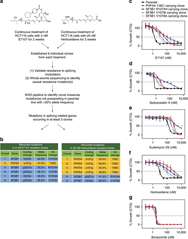
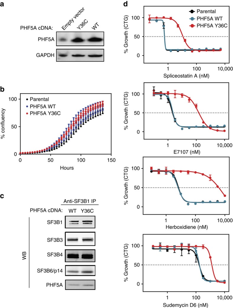
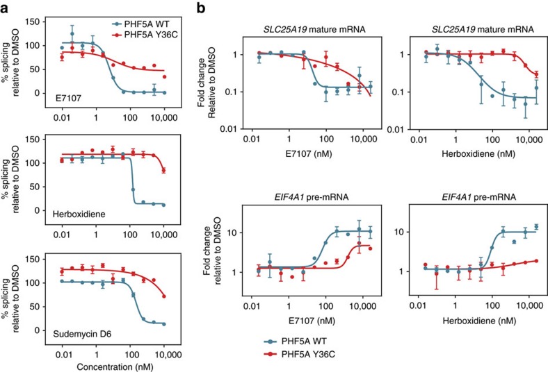
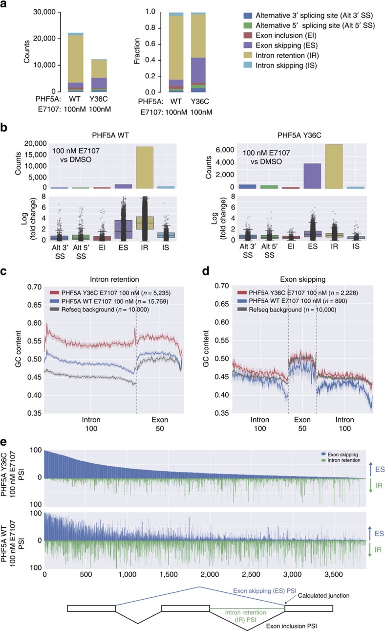
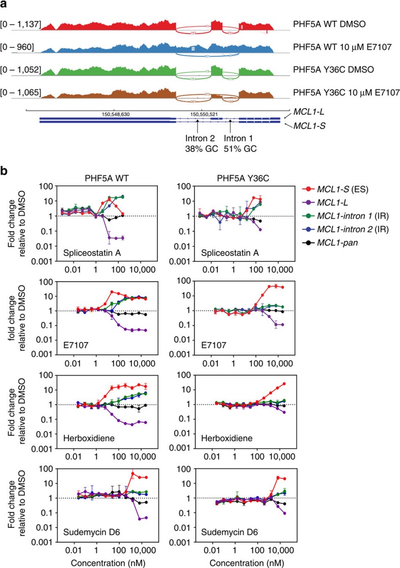
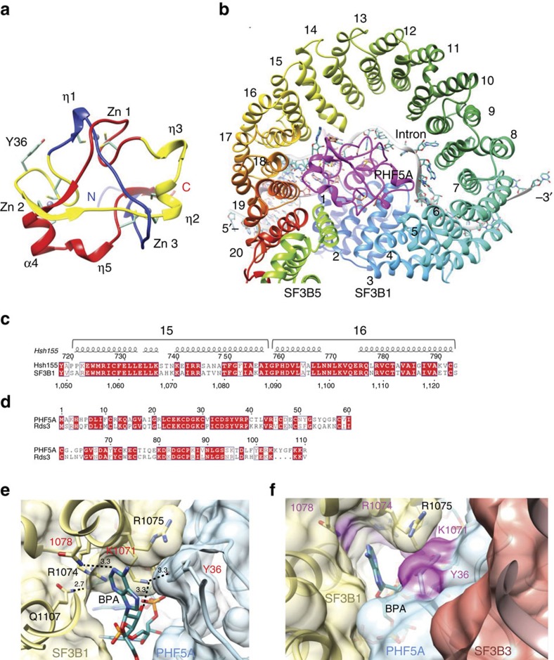
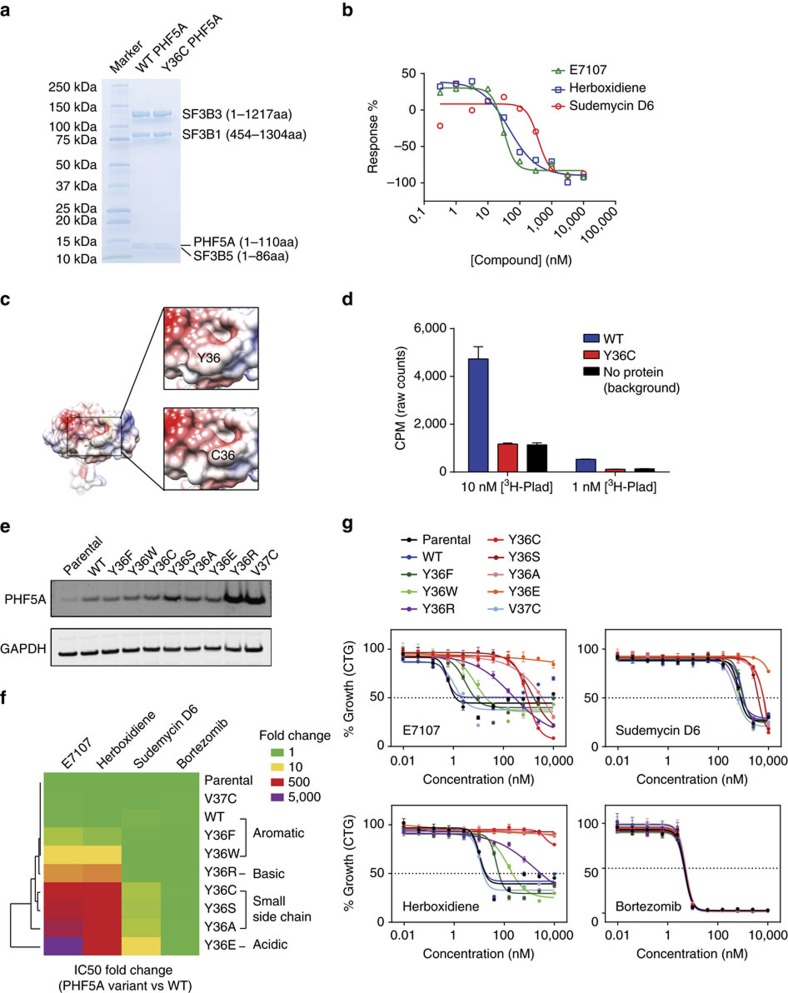
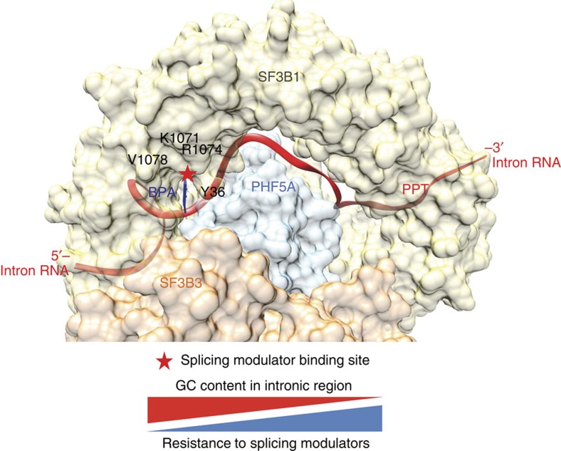
Pladienolide, herboxidiene and spliceostatin have been identified as splicing modulators that target SF3B1 in the SF3b subcomplex. Here we report that PHF5A, another component of this subcomplex, is also targeted by these compounds. Mutations in PHF5A-Y36, SF3B1-K1071, SF3B1-R1074 and SF3B1-V1078 confer resistance to these modulators, suggesting a common interaction site. RNA-seq analysis reveals that PHF5A-Y36C has minimal effect on basal splicing but inhibits the global action of splicing modulators. Moreover, PHF5A-Y36C alters splicing modulator-induced intron-retention/exon-skipping profile, which correlates with the differential GC content between adjacent introns and exons. We determine the crystal structure of human PHF5A demonstrating that Y36 is located on a highly conserved surface. Analysis of the cryo-EM spliceosome Bact complex shows that the resistance mutations cluster in a pocket surrounding the branch point adenosine, suggesting a competitive mode of action. Collectively, we propose that PHF5A-SF3B1 forms a central node for binding to these splicing modulators.


Conflict of interest statement

The authors are employees of H3 Biomedicine that has an interest in developing splicing modulators for therapeutics.

Figures

Figure 1
Figure 1. Recurrent splicing modulator-resistant mutations in PHF5A and SF3B1 identified by a chemogenomic approach.
(a) Experimental scheme of E7107 and herboxidiene-resistant clone generation and whole-exome sequencing (WXS) analysis. (b) Recurrent mutations in E7107 and herboxidiene-resistant clones. (cg) Seventy-two hours growth inhibition profiling (CellTiter-Glo cellular viability assay) of representative resistant clones' response to indicated compounds. Error bar indicates s.d. For E7107, herboxidiene and bortezomib, n=4; for spliceostatin A and sudemycin D6, n=2.
Figure 2
Figure 2. PHF5A-Y36C does not affect basal cellular functions but confers resistance to splicing modulators.
(a) Western blot analysis of PHF5A levels in parental, PHF5A WT-expressing and PHF5A Y36C-expressing HCT116 cells. GAPDH is shown as a loading control. (b) Proliferation of parental, WT PHF5A-expressing or Y36C PHF5A-expressing HCT116 cells as measured by the Incucyte imaging system. X axis indicates hours post seeding, and y axis indicates percent of confluency. Error bar indicates s.d., n=5. (c) Western blot analysis of indicated SF3b complex protein levels following anti-SF3B1 pull-down from nuclear extracts containing WT or Y36C PHF5A. (d) Seventy-two hours growth inhibition profiling (CellTiter-Glo cellular viability assay) of parental, PHF5A WT-expressing and PHF5A Y36C-expressing HCT116 cells in response to indicated splicing modulators. Error bar indicates s.d., n=2.
Figure 3
Figure 3. PHF5A-Y36C protects against splicing modulator induced mis-splicing.
(a) In vitro splicing assay in the presence of indicated splicing modulators in nuclear extracts containing WT or Y36C PHF5A. Error bar indicates s.d., n=4. (b) Taqman gene expression analysis of mature SLC25A19 mRNA levels and EIF4A1 pre-mRNA levels in either WT- or Y36C PHF5A-expressing cells treated with indicated splicing modulators. All data points were normalized to the corresponding DMSO-treated control samples and displayed in logarithmic scale on the y axis. Error bar indicates s.d., n=2.
Figure 4
Figure 4. Inhibition and modulation of the effect of E7107 on global splicing patterns by PHF5A-Y36C.
(a) Stacked bar graph of the counts (left panel) and fractions (right panel) of differential splicing events in each indicated treatment group as compared to DMSO controls. (b) Summary of the counts and log2 fold changes of differential splicing events in the indicated treatment group as compared to DMSO controls. Box shows the interquartile range (IQR) of the data set whereas the whiskers illustrate 1.5 × IQR. (c) Plot of average GC content within retained introns and downstream exons from E7107-induced intron-retention junctions. Each intron was normalized to 100 bins whereas each exon to 50 bins (see Methods for details). Dark line represents average GC content of each bin; shaded region indicates the 95% confidence interval. (d) Plot of average GC content within skipped-exons and both upstream (left) and downstream (right) introns from E7107-induced exon-skipping junctions. Each intron was normalized to 100 bins whereas each exon to 50 bins (see Methods for details). Dark line represents average GC content of each bin; shaded region indicates the 95% confidence interval. (e) Waterfall plot of the 3′ junction usage of 3,883 junctions (see text for details) in E7107 treated PHF5A Y36C (top) and WT (bottom) cells. X axis on both panels is ordered based on the ES PSI (percentage spliced in) value (large to small) of each junction in E7107-treated Y36C line. On y axis the PSI of either exon-skipping (ES, blue) or intron-retention (IR, green) of the same 3′ junction were shown. The scheme of PSI calculation is shown below waterfall plots.
Figure 5
Figure 5. PHF5A-Y36C alters the effects of splicing modulators on MCL1 splicing.
(a) Representative Sashimi plot of the production of different MCL1 isoforms under indicated treatment from either WT or Y36C PHF5A overexpressing cells. Total reads for each track are shown in the left. (b) Taqman gene expression analysis of indicated MCL1 isoforms in either WT (left panel) or Y36C (right panel) PHF5A expressing cells treated with splicing modulators. Error bar indicates s.d., n=2.
Figure 6
Figure 6. Crystal structure of human PHF5A.
(a) Ribbon diagram of PHF5A (PDB:5SYB). Zinc atoms are shown as grey balls and form the vertices of a near equilateral triangle. The secondary structural elements (α: helix, η:310 helix, β: strand) forming the sides of the trefoil knot are coloured blue, yellow and red arranged by their primary sequence. The N and C termini are labelled. Cysteine residues are shown as sticks as well as the critical Y36 residue. (b) Model of PHF5A in the yeast Bact complex. Yeast PHF5A (magenta), SF3B5 (neon green) and SF3B1 (rainbow colours according to HEAT repeat HR-1 to 20) formed a complex that made contacts to the RNA duplex base-paired by U2 snRNA (orange ribbon) and the branch point sequence (BPS), and as well as a single-stranded intron RNA at the downstream of BPS (grey ribbon and the atoms are coloured in cyan). (c) Sequence alignment of the HEAT repeat 15 and 16 where this part of Hsh155 formed adenine-binding site with Rds3. (d) Sequence alignment of PHF5A with Rds3. The sequence identity is 56%. (e) Potential configuration of human adenine-binding site showing interactions between PHF5A (light blue), SF3B1 (yellow) and intron RNA (cyan). (f) Surface view of the potential modulator-binding site composed by SF3B1 (yellow), PHF5A (light blue) and SF3B3 (orange). Drug-resistant residues were highlighted in magenta.
Figure 7
Figure 7. Characterization of the binding pocket of splicing modulator.
(a) Coomassie staining of the recombinant four-protein mini-complexes containing PHF5A-WT or PHF5A-Y36C used for Scintillation Proximity Assays. (b) The competitive titration curves of non-radioactive splicing modulators to 3H-labelled pladienolide analogue (10 nM) binding to the WT four protein complex. (c) Overall surface view of modelled C36 overlaid onto WT (Y36 show in cyan stick) and zoom-in PHF5A surface view at Y36 and C36. Surface potential coloured in red: −8 kBT/e, blue: +8 kBT/e and white: 0 kBT/e was calculated by APBS. (d) Scintillation Proximity Assay of the 3H-labelled pladienolide analogue (10 and 1 nM) binding to protein complexes containing WT or Y36C PHF5A. Error bar indicates s.d., n=2. (e) Western blot analysis of PHF5A levels in parental and indicated PHF5A variants expressing HCT116 cells. GAPDH is shown as a loading control. (f) Unsupervised clustering heatmap of the IC50 shift between indicated PHF5A variant expressing cell lines as compared to WT cell lines. The shift is shown as fold changes and calculated from IC50 values extracted from dose–response curves in (g). Each row represents indicated PHF5A variant and each column corresponds to indicated compound. Colour key is shown on the top right corner. (g) Seventy-two hours growth inhibition profiling (CellTiter-Glo cellular viability assay) of parental and indicated PHF5A variant expressing HCT116 cells' response to indicated compounds. Error bar indicates s.d., n=3.
Figure 8
Figure 8. Model of splicing modulator interaction with the SF3b complex at the BPA-binding pocket constituted by PHF5A and SF3B1.
The molecular surface representation of the protein complex SF3B1 (yellow), PHF5A (blue) and SF3B3 (orange). The intron RNA is shown as red ribbon, with branch point adenosine (BPA) in dark blue. The common splicing modulators binding site is indicated by a star with the approximate positions of the surrounding residues for which resistance mutations were identified. The figure was generated using the yeast Bact complex coordinates. The schematic model indicates the inverse correlation between the GC content of the intron sequence and their resistance to splicing modulation. Specifically, high GC content intron substrates are weaker substrates that show more sensitivity or less resistance to splicing modulators.

References

    1. Matera A. G. & Wang Z. A day in the life of the spliceosome. Nat. Rev. Mol. Cell Biol. 15, 108–121 (2014). - PMC - PubMed
    1. Scotti M. M. & Swanson M. S. RNA mis-splicing in disease. Nat. Rev. Genet. 17, 19–32 (2016). - PMC - PubMed
    1. Bonnal S., Vigevani L. & Valcarcel J. The spliceosome as a target of novel antitumour drugs. Nat. Rev. Drug Discov. 11, 847–859 (2012). - PubMed
    1. Naryshkin N. A. et al.. Motor neuron disease. SMN2 splicing modifiers improve motor function and longevity in mice with spinal muscular atrophy. Science 345, 688–693 (2014). - PubMed
    1. Eskens F. A. et al.. Phase I pharmacokinetic and pharmacodynamic study of the first-in-class spliceosome inhibitor E7107 in patients with advanced solid tumors. Clin. Cancer Res. 19, 6296–6304 (2013). - PubMed

Publication types

MeSH terms