

Designing lead-free antiferroelectrics for energy storage
- PMID: 28555655
- PMCID: PMC5499206
- DOI: 10.1038/ncomms15682
Designing lead-free antiferroelectrics for energy storage
Abstract
Dielectric capacitors, although presenting faster charging/discharging rates and better stability compared with supercapacitors or batteries, are limited in applications due to their low energy density. Antiferroelectric (AFE) compounds, however, show great promise due to their atypical polarization-versus-electric field curves. Here we report our first-principles-based theoretical predictions that Bi1-xRxFeO3 systems (R being a lanthanide, Nd in this work) can potentially allow high energy densities (100-150 J cm-3) and efficiencies (80-88%) for electric fields that may be within the range of feasibility upon experimental advances (2-3 MV cm-1). In addition, a simple model is derived to describe the energy density and efficiency of a general AFE material, providing a framework to assess the effect on the storage properties of variations in doping, electric field magnitude and direction, epitaxial strain, temperature and so on, which can facilitate future search of AFE materials for energy storage.
Conflict of interest statement
The authors declare no competing financial interests.
Figures
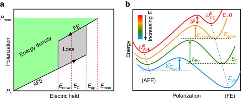
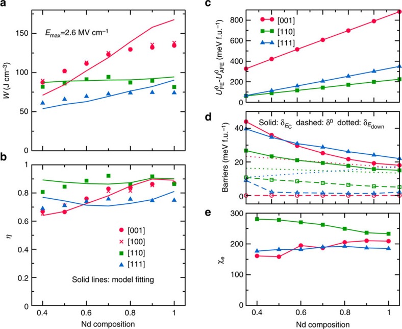
 being the variable for each E orientation with linear dependence on the composition. (c–e) Model parameters at various compositions and E-field orientations. (c) The zero-field energy difference between the AFE and FE phases. (d) The FE-to-AFE barrier at E=0 (δ0, dashed lines), Edown (
 , dotted lines) and EC (
 , solid lines). (e) The dielectric susceptibility.
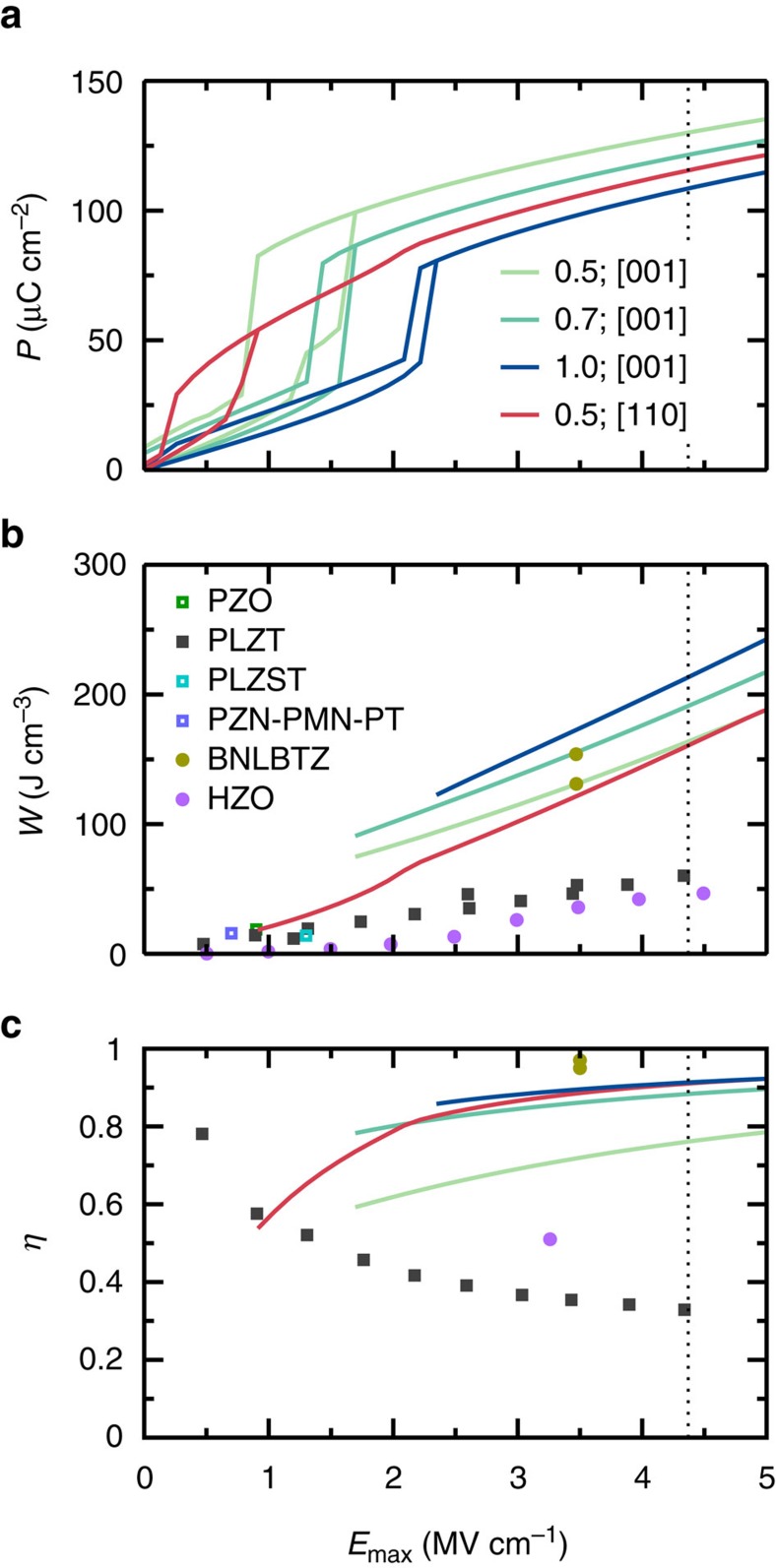
Similar articles
-
Ultrahigh Energy Efficiency and Large Discharge Energy Density in Flexible Dielectric Nanocomposites with Pb0.97La0.02(Zr0.5SnxTi0.5-x)O3 Antiferroelectric Nanofillers.ACS Appl Mater Interfaces. 2020 Mar 18;12(11):12847-12856. doi: 10.1021/acsami.9b23074. Epub 2020 Mar 4. ACS Appl Mater Interfaces. 2020. PMID: 32084310
-
Enhanced energy storage in antiferroelectrics via antipolar frustration.Nature. 2025 Jan;637(8048):1104-1110. doi: 10.1038/s41586-024-08505-7. Epub 2025 Jan 29. Nature. 2025. PMID: 39880993
-
Achieving Remarkable Amplification of Energy-Storage Density in Two-Step Sintered NaNbO3-SrTiO3 Antiferroelectric Capacitors through Dual Adjustment of Local Heterogeneity and Grain Scale.ACS Appl Mater Interfaces. 2020 Apr 29;12(17):19467-19475. doi: 10.1021/acsami.0c00831. Epub 2020 Apr 14. ACS Appl Mater Interfaces. 2020. PMID: 32250098
-
Anti-Ferroelectric Ceramics for High Energy Density Capacitors.Materials (Basel). 2015 Nov 25;8(12):8009-8031. doi: 10.3390/ma8125439. Materials (Basel). 2015. PMID: 28793694 Free PMC article. Review.
-
Electrochemical capacitors: mechanism, materials, systems, characterization and applications.Chem Soc Rev. 2016 Oct 24;45(21):5925-5950. doi: 10.1039/c5cs00580a. Chem Soc Rev. 2016. PMID: 27545205 Review.
Cited by
-
Liberating a hidden antiferroelectric phase with interfacial electrostatic engineering.Sci Adv. 2022 Feb 4;8(5):eabg5860. doi: 10.1126/sciadv.abg5860. Epub 2022 Feb 2. Sci Adv. 2022. PMID: 35108054 Free PMC article.
-
Giant energy density and high efficiency achieved in bismuth ferrite-based film capacitors via domain engineering.Nat Commun. 2018 May 8;9(1):1813. doi: 10.1038/s41467-018-04189-6. Nat Commun. 2018. PMID: 29739938 Free PMC article.
-
Giant energy density nitride dielectrics enabled by a paraelectric-metaparaelectric phase transition.Nat Commun. 2025 Apr 3;16(1):3191. doi: 10.1038/s41467-025-58267-7. Nat Commun. 2025. PMID: 40180940 Free PMC article.
-
Quantum criticality at cryogenic melting of polar bubble lattices.Nat Commun. 2023 Nov 30;14(1):7874. doi: 10.1038/s41467-023-43598-0. Nat Commun. 2023. PMID: 38036499 Free PMC article.
-
Continuously tunable ferroelectric domain width down to the single-atomic limit in bismuth tellurite.Nat Commun. 2022 Oct 6;13(1):5903. doi: 10.1038/s41467-022-33617-x. Nat Commun. 2022. PMID: 36202850 Free PMC article.
References
-
- Gross R., Leach M. & Bauen A. Progress in renewable energy. Environ. Int. 29, 105–122 (2003). - PubMed
-
- Haspert L. C., Gillette E., Lee S. B. & Rubloff G. W. Perspective: hybrid systems combining electrostatic and electrochemical nanostructures for ultrahigh power energy storage. Energy Environ. Sci. 6, 2578 (2013).
-
- Sherrill S. A., Banerjee P., Rubloff G. W. & Lee S. B. High to ultra-high power electrical energy storage. Phys. Chem. Chem. Phys. 13, 20714 (2011). - PubMed
-
- Hao X. A review on the dielectric materials for high energy-storage application. J. Adv. Dielectr. 03, 1330001 (2013).
-
- Ma B., Kwon D. K., Narayanan M. & (Balu) Balachandran U. Dielectric properties and energy storage capability of antiferroelectric Pb0.92La0.08Zr0.95Ti0.05O3 film-on-foil capacitors. J. Mater. Res. 24, 2993–2996 (2009).
Publication types
LinkOut - more resources
Full Text Sources
Other Literature Sources
