

Cellular fluid shear stress on implant surfaces-establishment of a novel experimental set up
- PMID: 28567712
- PMCID: PMC5451379
- DOI: 10.1186/s40729-017-0085-3
Cellular fluid shear stress on implant surfaces-establishment of a novel experimental set up
Abstract
Background: Mechanostimuli of different cells can affect a wide array of cellular and inter-cellular biological processes responsible for dental implant healing. The purpose of this in vitro study was to establish a new test model to create a reproducible flow-induced fluid shear stress (FSS) of osteoblast cells on implant surfaces.
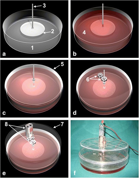
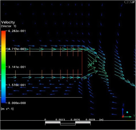
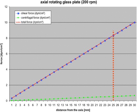
Methods: As FSS effects on osteoblasts are detectable at 10 dyn/cm2, a custom-made flow chamber was created. Computer-aided verification of circulation processes was performed. In order to verify FSS effects, cells were analysed via light and fluorescence microscopy.
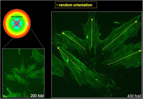
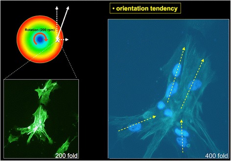
Results: Utilising computer-aided simulations, the underside of the upper plate was considered to have optimal conditions for cell culturing. At this site, a flow-induced orientation of osteoblast cell clusters and an altered cell morphology with cellular elongation and alteration of actin fibres in the fluid flow direction was detected.
Conclusions: FSS simulation using this novel flow chamber might mimic the peri-implant situation in the phase of loaded implant healing. With this FSS flow chamber, osteoblast cells' sensitivity to FSS was verified in the form of morphological changes and cell re-clustering towards the direction of the flow. Different shear forces can be created simultaneously in a single experiment.
Keywords: Bioengineering; Biomechanics; Cell biology; Dental implant materials; Implant healing; Osteoblast; Stress analysis.
Figures
Similar articles
-
A quantitative study on morphological responses of osteoblastic cells to fluid shear stress.Acta Biochim Biophys Sin (Shanghai). 2010 Mar 15;42(3):195-201. doi: 10.1093/abbs/gmq004. Acta Biochim Biophys Sin (Shanghai). 2010. PMID: 20213044
-
Novel cone-and-plate flow chamber with controlled distribution of wall fluid shear stress.Comput Biol Med. 2019 Mar;106:140-148. doi: 10.1016/j.compbiomed.2019.01.014. Epub 2019 Jan 25. Comput Biol Med. 2019. PMID: 30721821
-
Impact of flow shear stress on morphology of osteoblast-like IDG-SW3 cells.J Bone Miner Metab. 2018 Sep;36(5):529-536. doi: 10.1007/s00774-017-0870-3. Epub 2017 Oct 12. J Bone Miner Metab. 2018. PMID: 29027016 Free PMC article.
-
miRNA expression profile during fluid shear stress-induced osteogenic differentiation in MC3T3-E1 cells.Chin Med J (Engl). 2013;126(8):1544-50. Chin Med J (Engl). 2013. PMID: 23595392
-
[A review on progress of in vitro research of fluid shear stress influence on signaling networks of osteoblasts].Sheng Wu Yi Xue Gong Cheng Xue Za Zhi. 2012 Dec;29(6):1207-11. Sheng Wu Yi Xue Gong Cheng Xue Za Zhi. 2012. PMID: 23469558 Review. Chinese.
Cited by
-
Effects of interfacial micromotions on vitality and differentiation of human osteoblasts.Bone Joint Res. 2018 Apr 12;7(2):187-195. doi: 10.1302/2046-3758.72.BJR-2017-0228.R1. eCollection 2018 Feb. Bone Joint Res. 2018. PMID: 29682285 Free PMC article.
-
Changes in interstitial fluid flow, mass transport and the bone cell response in microgravity and normogravity.Bone Res. 2022 Nov 21;10(1):65. doi: 10.1038/s41413-022-00234-9. Bone Res. 2022. PMID: 36411278 Free PMC article. Review.
References
-
- Bancroft GN, Sikavitsas VI, van den Dolder J, Sheffield TL, Ambrose CG, Jansen JA, et al. Fluid flow increases mineralized matrix deposition in 3D perfusion culture of marrow stromal osteoblasts in a dose-dependent manner. Proc Natl Acad Sci U S A. 2002;99(20):12600–12605. doi: 10.1073/pnas.202296599. - DOI - PMC - PubMed
LinkOut - more resources
Full Text Sources
Other Literature Sources
Research Materials
