. 2017 Jun 1;7(1):2471.
doi: 10.1038/s41598-017-02645-9.

In vivo imaging of uterine cervix with a Mueller polarimetric colposcope

Affiliations

In vivo imaging of uterine cervix with a Mueller polarimetric colposcope

Jérémy Vizet et al. Sci Rep. .

Abstract

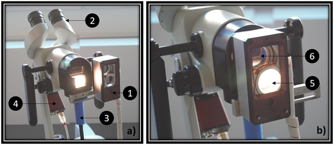
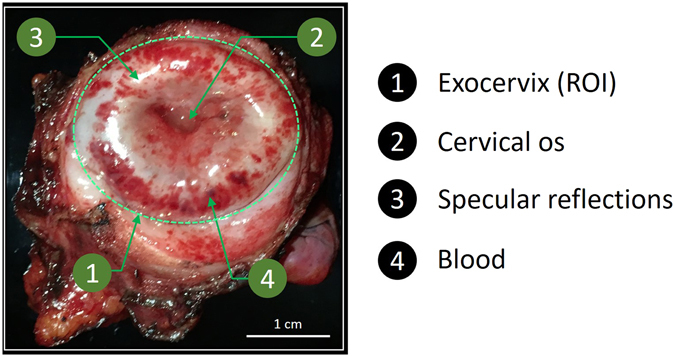
Mueller polarimetric imaging enables the detection and quantification of modifications of the collagen fibers in the uterine cervix due to the development of a precancerous lesion. This information is not accessible through the use of the classic colposcope, a low magnification microscope used in current practice for cervical cancer screening. However, the in vivo application of Mueller polarimetric imaging poses an instrumental challenge: the device should be sufficiently compact, while still being able to perform fast and accurate acquisition of Mueller matrices in real-world conditions. In this study, the first wide field Mueller Polarimetric Colposcope (MPC) for the in vivo analysis of uterine cervix is presented. The MPC has been fabricated by grafting a miniaturized Mueller polarimetric imager on a classic colposcope. This new imaging tool performs the fast acquisition of Mueller polarimetric images, thus eliminating any blurring effects due to patient movements. It can be easily used by a practitioner with little change to their existing practice. Finally, the MPC was tested in vivo on a number of patients in the field.


Conflict of interest statement

The authors declare that they have no competing interests.

Figures

Figure 1
Figure 1
(a) Photo of the entire MPC system (1: Polarimetric head, 2: Binoculars for stereoscopic vision of the uterine cervix, 3: Liquid light guide, 4: CCD camera). The polarimetric head is in the “OFF” position, and permit classical colposcopic observations. (b) Polarimetric system can be slid on the “ON” position to permit the acquisition of Mueller polarimetric images (5: Polarization States Generator (PSG), 6: Polarization States Analyzer (PSA)).
Figure 2
Figure 2
Unpolarized RGB picture of the uterine cervix from a complete hysterectomy from a patient with normal Pap smear.
Figure 3
Figure 3
Comparison of intensity and polarimetric images obtained with the MIP and the MPC on the ex vivo uterine cervix shown in Fig. 2. (ad) MIP Intensity image and polarimetric images of Depolarization (Δ), Retardance (R) and Azimuth (α) respectively for an acquisition time of 64 s. (eh) the same parameters acquired by the MPC for an acquisition time of 25 s. (il) the same parameters acquired by the MPC for an acquisition time of 1.6 s. (mp) histograms of Intensity, Depolarization, Retardance and Azimuth images respectively for both instruments at different acquisition times. All the histograms were calculated inside the ROI delineated by the yellow line in Fig. 3(a). White and orange dotted lines in Fig. 3(i) delimit two different areas that will be analyzed more in detail in Fig. 4.
Figure 4
Figure 4
Comparison between histograms of Depolarization, Retardance and Azimuth measured with the MIP in 64 s (reference), with the MPC in 25 s and with the MPC in 1.6 s for the zone selected around the thrombotic zone (delineated by the orange dotted line in Fig. 3(i)) and the zone selected outside the thrombotic region (delineated by the white dotted line in Fig. 3(i)).
Figure 5
Figure 5
In vivo unpolarized RGB pictures of two uterine cervices. (a) Healthy uterine cervix (Cervix 1). (b) Healthy uterine cervix with polyp (Cervix 2).
Figure 6
Figure 6
Comparison between intensity and polarimetric images of the in vivo uterine cervices shown in Fig. 5. (ad) MPC intensity image and polarimetric images of Depolarization (Δ), Retardance (R) and Azimuth (α) respectively, for Cervix 1; (eh) the same parameters for Cervix 2. Corresponding histograms of Intensity, Depolarization, Retardance and Azimuth images for both samples are plotted in the Fig. 6(i–l) respectively. Histograms were calculated inside the three ROI delineated by the yellow solid lines in Fig. 6(a,e) (Zone 1, Zone 2 and Zone 3). Red line in Fig. 6(h), solid and dotted black lines in Fig. 6(d,h) delineate three areas that will be analyzed more in detail in Fig. 7.
Figure 7
Figure 7
Histograms of Intensity (a) and Azimuth (b) of areas delineated in Fig. 6(d,h).
Figure 8
Figure 8
(a,b) Unpolarized RGB pictures of Cervix 1 and Cervix 2 respectively. (c,d) Standard deviation of the Azimuth computed for each pack of 3 × 3 pixels.

References

    1. Ghosh N, Vitkin IA. Tissue polarimetry: concepts, challenges, applications, and outlook. Journal of biomedical optics. 2011;16:110801–11080129. doi: 10.1117/1.3652896. - DOI - PubMed
    1. Jacques SL, Ramella-Roman JC, Lee K. Imaging skin pathology with polarized light. Journal of biomedical optics. 2002;7:329–340. doi: 10.1117/1.1484498. - DOI - PubMed
    1. Smith, M. H., Burke, P. D., Lompado, A., Tanner, E. A. & Hillman, L. W. Mueller matrix imaging polarimetry in dermatology. In BiOS 2000 The International Symposium on Biomedical Optics 210–216 (International Society for Optics and Photonics, 2000).
    1. Smith, M. H. Interpreting mueller matrix images of tissues. In BiOS 2001 The International Symposium on Biomedical Optics 82–89 (International Society for Optics and Photonics, 2001).
    1. Wang, W. et al. Investigation on the potential of mueller matrix imaging for digital staining. Journal of biophotonics9999 (2015). - PubMed

MeSH terms