. 2017 Jun;52(6):1576-1590.
doi: 10.1109/JSSC.2017.2686580. Epub 2017 Apr 27.

A Multi-Functional Microelectrode Array Featuring 59760 Electrodes, 2048 Electrophysiology Channels, Stimulation, Impedance Measurement and Neurotransmitter Detection Channels

Affiliations

A Multi-Functional Microelectrode Array Featuring 59760 Electrodes, 2048 Electrophysiology Channels, Stimulation, Impedance Measurement and Neurotransmitter Detection Channels

Jelena Dragas et al. IEEE J Solid-State Circuits. 2017 Jun.

Abstract

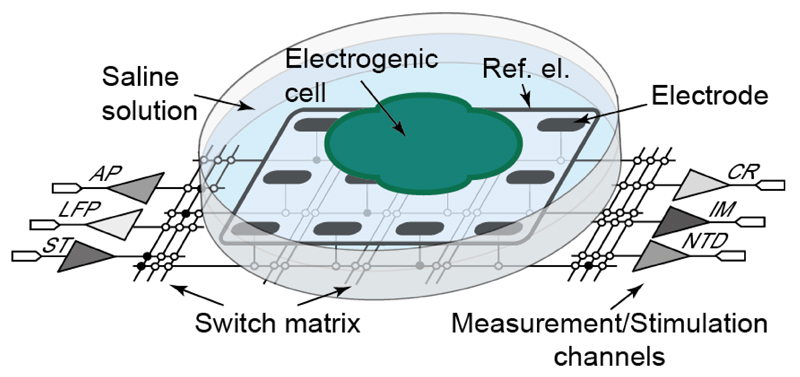
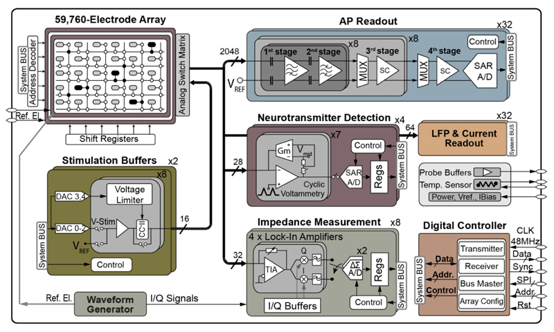
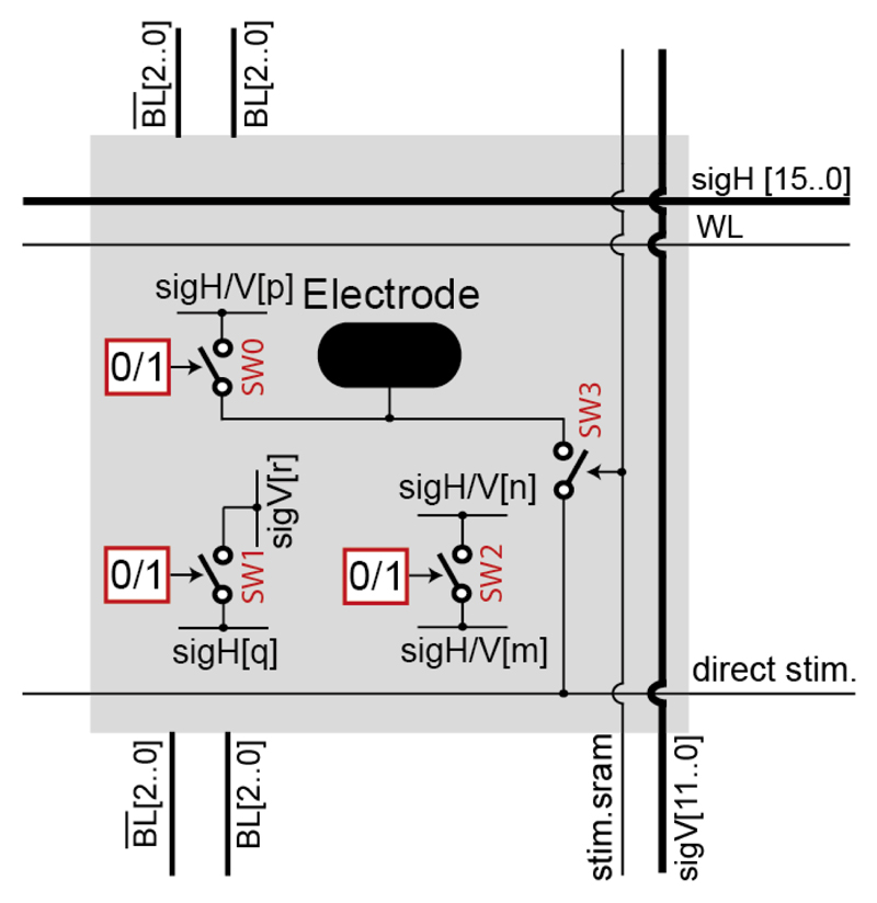
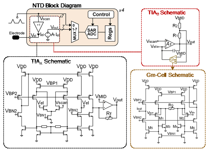
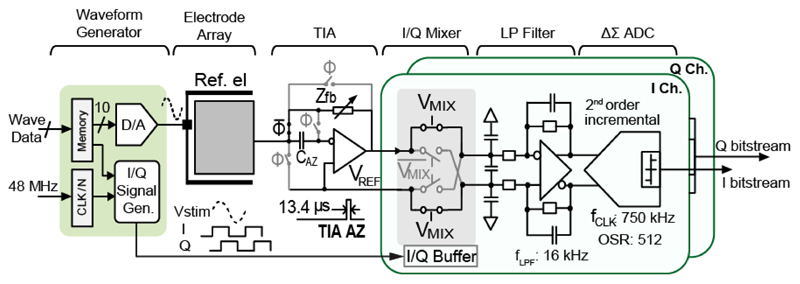
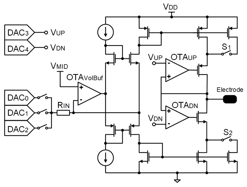
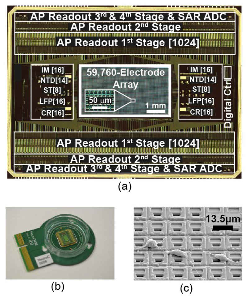
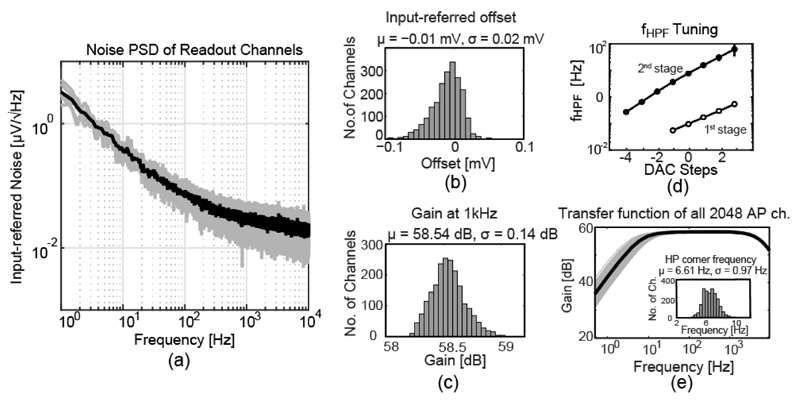
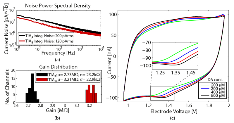
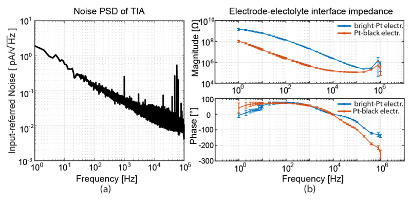
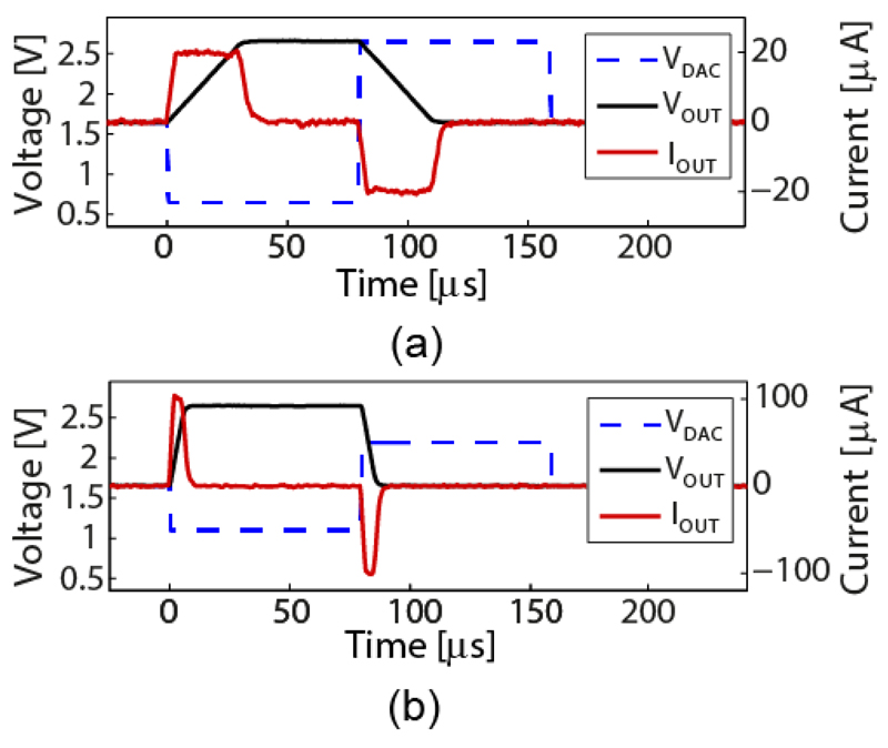
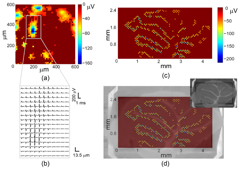
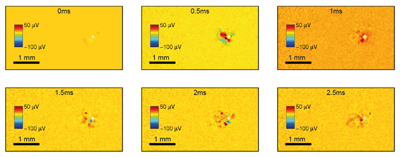
Biological cells are characterized by highly complex phenomena and processes that are, to a great extent, interdependent. To gain detailed insights, devices designed to study cellular phenomena need to enable tracking and manipulation of multiple cell parameters in parallel; they have to provide high signal quality and high spatiotemporal resolution. To this end, we have developed a CMOS-based microelectrode array system that integrates six measurement and stimulation functions, the largest number to date. Moreover, the system features the largest active electrode array area to date (4.48×2.43 mm2) to accommodate 59,760 electrodes, while its power consumption, noise characteristics, and spatial resolution (13.5 μm electrode pitch) are comparable to the best state-of-the-art devices. The system includes: 2,048 action-potential (AP, bandwidth: 300 Hz to 10 kHz) recording units, 32 local-field-potential (LFP, bandwidth: 1 Hz to 300 Hz) recording units, 32 current recording units, 32 impedance measurement units, and 28 neurotransmitter detection units, in addition to the 16 dual-mode voltage-only or current/voltage-controlled stimulation units. The electrode array architecture is based on a switch matrix, which allows for connecting any measurement/stimulation unit to any electrode in the array and for performing different measurement/stimulation functions in parallel.

Keywords: extracellular recording and stimulation; high channel count; high-density microelectrode array (HD-MEA); impedance spectroscopy; low noise; low power; multi-functionality; neural interface; neurotransmitter detection; pre-charging; pseudo-resistor; switch matrix.


Figures

Fig. 1
Fig. 1
Illustration of the multi-functional, switch-matrix-based HD-MEA system featuring action potential (AP) readout, local field potential (LFP) readout, current readout (CR), impedance measurement (IM), neurotransmitter detection (NTD) and stimulation (ST) channels.
Fig. 2
Fig. 2
Block diagram of the multi-functional MEA system.
Fig. 3
Fig. 3
Block diagram of an array pixel. Switch SW0 connects the electrode to either a horizontal (sigH) or a vertical (sigV) wire. SW1 connects two intersecting wires, SW2 connects a pair of parallel wires. m, n, p, q ∈ [0,15], r ∈ [0,11].
Fig. 4
Fig. 4
AP recording channels. (a) Block diagram of the 2048 AP recording channels. (b) Open-loop amplifier (A1) used in the first stage and its constant-gm bias circuit. (c) Two types of pseudo resistors and their bias circuits. (d) MOSFET-only R-2R current DAC for tuning high-pass corner frequencies.
Fig. 5
Fig. 5
The pre-charging technique. (a) Schematic of a portion of the SC third-stage amplifier, drawn as single-ended circuit for brevity. (b) A sketch of Vo2_i with/without using the pre-charging technique.
Fig. 6
Fig. 6
Block diagram of the neurotransmitter detection channel and schematics of TIAA, TIAB, and the Gm cell.
Fig. 7
Fig. 7
Schematic of the lock-in-amplifier-based impedance measurement channel.
Fig. 8
Fig. 8
Schematic of the current/voltage-controlled stimulation buffer.
Fig. 9
Fig. 9
(a) Chip micrograph. (b) Bio-compatible chip packaging and PCB. (c) SEM image of the chip surface, showing in-house post-processed Pt-electrodes and dissociated primary rat cortical neurons, cultured on top.
Fig. 10
Fig. 10
(a) Noise power spectral density of the AP recording channel including the ADC. (b) Input-referred offset distribution of the 2048 AP channels. (c) Gain distribution of the 2048 AP channels. (d) The first- and second-stage HPF corner frequency (fHPF) tuned by the current DAC. (e) Transfer function of 2048 AP channels and fHPF distribution.
Fig. 11
Fig. 11
(a) Noise power spectral density of TIAA and TIAB including multiplexer and ADC. b) Gain distribution across 3 chips. (c) Recorded FSCV results for concentrations of 200 μM, 300 μM, 400 μM and 500 μM dopamine in 0.1 M PBS. TIAB connected to a single electrode has been used. Each of the curves is an average over 98 scans applied within 1 s.
Fig. 12
Fig. 12
(a) Noise power spectral density of the TIA with Rf = 10 MΩ. (b) Magnitude and phase of the bright Pt and Pt-black electrode impedance in a frequency range between 1 Hz and 1 MHz, averaged over 6 and 8 electrodes for bright Pt and Pt-black, respectively.
Fig. 13
Fig. 13
Voltage (black) and current (red) waveforms, generated by the stimulation buffer operated in current/voltage-controlled mode and connected to a 610 pF external load. The blue dashed line indicates the input waveform. (a) Low-current mode configuration, (b) High-current mode configuration.
Fig. 14
Fig. 14
(a) Average negative peak amplitudes, recorded by an HD electrode configuration (45×45 pixels, 607.5×607.5 μm2) from dissociated primary rat cortical neurons. Each pixel in the image corresponds to an electrode. (b) AP waveforms, recorded in a sub-region of (a), averaged 20 times. (c) Mouse cerebellar slice electrical activity, recorded with a single sparse configuration of 2000 electrodes. The recording electrodes are displayed 9 times larger than their original size for visual clarity. (d) Overlap of (c) and a microscopy image of the slice (inset).
Fig. 15
Fig. 15
Six frames showing 2.5 ms of evoked neuronal activity from a culture of dissociated rat cortical neurons. A biphasic voltage-controlled pulse (300 mV phase amplitude and 200 μs phase duration) was applied to a single electrode (white cross), while the other electrodes were scanned for recording from the entire array (4.48×2.43 mm2) at full spatial resolution (13.5 μm electrode pitch). 100 averages were computed for each electrode and temporally aligned with respect to the stimulation pulses.

References

    1. Uhlhaas PJ, Singer W. Review Neural Synchrony in Brain Disorders: Relevance for Cognitive Dysfunctions and Pathophysiology. Neuron J. 2006;52:155–168. - PubMed
    1. Roham M, Covey DP, Daberkow DP, et al. A wireless IC for time-share chemical and electrical neural recording. IEEE J Solid-State Circuits. 2009;44(12):3645–3658.
    1. Nazari MH, Mazhab-Jafari H, Leng L, Guenther A, Genov R. CMOS neurotransmitter microarray: 96-channel integrated potentiostat with on-die microsensors. IEEE Trans Biomed Circuits Syst. 2013;7(3):338–348. - PubMed
    1. Guo J, Ng W, Yuan J, Li S, Chan M. A 200-Channel Area-Power-Efficient Chemical and Electrical Dual-Mode Acquisition IC for the Study of Neurodegenerative Diseases. IEEE Trans Biomed Circuits Syst. 2016;10(3):567–578. - PubMed
    1. Ross JD, O'Connor SM, Blum Ra, Brown Ea, DeWeerth SP. Multielectrode impedance tuning: reducing noise and improving stimulation efficacy. Conf Proc IEEE Eng Med Biol Soc. 2004;6:4115–4117. - PubMed