Review
. 2017 Jul;28(5):434-440.
doi: 10.1080/09537104.2017.1319047. Epub 2017 Jun 5.

Application of microfluidic devices in studies of thrombosis and hemostasis

Affiliations
Review

Application of microfluidic devices in studies of thrombosis and hemostasis

Changjie Zhang et al. Platelets. 2017 Jul.

Abstract

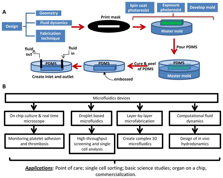
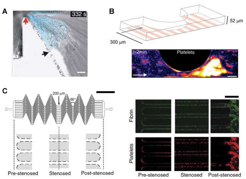
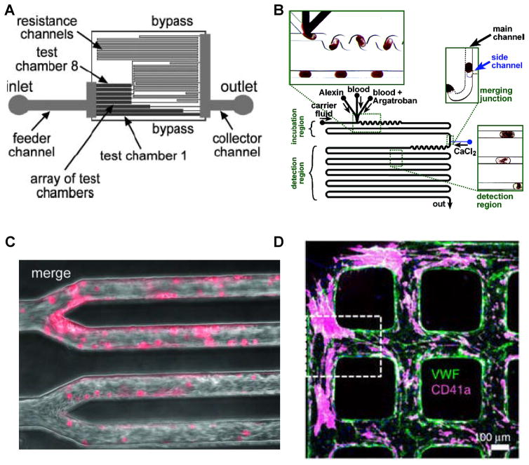
Due to the importance of fluid flow during thrombotic episodes, it is quite appropriate to study clotting and bleeding processes in devices that have well-defined fluid shear environments. Two common devices for applying these defined shear stresses include the cone-and-plate viscometer and parallel-plate flow chamber. While such tools have many salient features, they require large amounts of blood or other protein components. With growth in the area of microfluidics over the last two decades, it has become feasible to miniaturize such flow devices. Such miniaturization not only enables saving of precious samples but also increases the throughput of fluid shear devices, thus enabling the design of combinatorial experiments and making the technique more accessible to the larger scientific community. In addition to simple flows that are common in traditional flow apparatus, more complex geometries that mimic stenosed arteries and the human microvasculature can also be generated. The composition of the microfluidics cell substrate can also be varied for diverse basic science investigations, and clinical investigations that aim to assay either individual patient coagulopathy or response to anti-coagulation treatment. This review summarizes the current state of the art for such microfluidic devices and their applications in the field of thrombosis and hemostasis.

Keywords: PDMS; VWF; complex flow; flow chamber; fluid shear; microfluidics; platelets; point-of-care; stenosis; thrombosis.


Conflict of interest statement

Declaration of Interest

This work was supported by the National Institutes of Health grant HL77258, and American Heart Association award 161RG27770071.

Figures

Figure 1
Figure 1. Fabrication of microfluidics flow cells using polydimethylsiloxane replica molding
A. Fabrication starts with the design of the geometry and fluid dynamics that are of interest. The photolithography steps make use of the negative photoresist, e.g. SU-8. Exposure of this resist to UV radiation in the presence of the pattern mask results in the master mold. Then polydimethylsiloxane (PDMS) is used to cast microfluidic devices containing pre-designed structures reflected by the mold. In the final step, the PDMS mold is peeled from the master template and assembled into a flow device. B. Design and applications of microfluidics. Online figure is available in color.
Figure 2
Figure 2. Microfluidic devices to study platelet adhesion in post-stenotic region
In all examples, platelet adhesion and thrombus formation is observed in the post-stenotic downstream region, in the ‘shear deceleration zone’. All studies measure platelet aggregation using whole blood. A. Model microfluidics channel incorporating fixed 90% stenosis. Wall shear rate changes abruptly from 1800/s upstream to 200/s in the shear deceleration expansion zone. Scale bar=10μm (ref. [28]). B. 300 × 52 μm flow chamber with confluent endothelial/HUVEC substrate. Platelet aggregates formed in whole blood, in a shear dependent manner, are shown using pseudo coloring of fluorescent platelets. Scale bar=100μm (ref. [29]). C. Schematic to left showing a region of flow acceleration to the left (‘pre-stenosed’) and flow deceleration to the right (‘post-stenosed’). In between are 12 parallel 200 × 75 μm channels with a series of 60° angle turns. Right panel are representative images showing fibrin (top, green) and adhered platelets (bottom, red), prominently in the post-stenotic region (ref. [50]). Online figure is available in color. All figures are reproduced with permission.
Figure 3
Figure 3. Different geometries in advanced microfluidic devices
A. Inclusion of resistance channels to simulate different shear stresses on a single chip (ref. [52]). B. Testing of anti-coagulant (argatroban) in small plugs (ref. [53]). C. Microvascular clots (pink) formed upon perfusing blood into channels containing TNF-α activated endothelial cells (ref. [57]). D. VWF deposited in 3D endothelialized microfluidic channels. Platelet thrombi (pink) are seen decorated on VWF strings (green) (ref. [56]). Online figure is available in color. All figures are taken from cited references, with permission.

References

    1. Enderle J, Blanchard S, Bronzino J. Introduction to Biomedical Engineering. San Diego, CA: 2000. Cardiovascular mechanics; pp. 467–535.
    1. Gogia S, Neelamegham S. Role of fluid shear stress in regulating VWF structure, function and related blood disorders. Biorheology. 2015;52(5–6):319–35. - PMC - PubMed
    1. Jackson SP. Arterial thrombosis--insidious, unpredictable and deadly. Nat Med. 2011;17(11):1423–36. - PubMed
    1. Bagot CN, Arya R. Virchow and his triad: a question of attribution. Br J Haematol. 2008;143(2):180–90. - PubMed
    1. Pugh N, et al. Dynamic analysis of platelet deposition to resolve platelet adhesion receptor activity in whole blood at arterial shear rate. Platelets. 2015;26(3):216–9. - PMC - PubMed

LinkOut - more resources