Angle-ply biomaterial scaffold for annulus fibrosus repair replicates native tissue mechanical properties, restores spinal kinematics, and supports cell viability
- PMID: 28587986
- PMCID: PMC5832042
- DOI: 10.1016/j.actbio.2017.06.006
Angle-ply biomaterial scaffold for annulus fibrosus repair replicates native tissue mechanical properties, restores spinal kinematics, and supports cell viability
Abstract
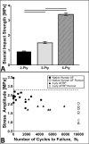
Annulus fibrosus (AF) damage commonly occurs due to intervertebral disc (IVD) degeneration/herniation. The dynamic mechanical role of the AF is essential for proper IVD function and thus it is imperative that biomaterials developed to repair the AF withstand the mechanical rigors of the native tissue. Furthermore, these biomaterials must resist accelerated degradation within the proteolytic environment of degenerate IVDs while supporting integration with host tissue. We have previously reported a novel approach for developing collagen-based, multi-laminate AF repair patches (AFRPs) that mimic the angle-ply architecture and basic tensile properties of the human AF. Herein, we further evaluate AFRPs for their: tensile fatigue and impact burst strength, IVD attachment strength, and contribution to functional spinal unit (FSU) kinematics following IVD repair. Additionally, AFRP resistance to collagenase degradation and cytocompatibility were assessed following chemical crosslinking. In summary, AFRPs demonstrated enhanced durability at high applied stress amplitudes compared to human AF and withstood radially-directed biaxial stresses commonly borne by the native tissue prior to failure/detachment from IVDs. Moreover, FSUs repaired with AFRPs and nucleus pulposus (NP) surrogates had their axial kinematic parameters restored to intact levels. Finally, carbodiimide crosslinked AFRPs resisted accelerated collagenase digestion without detrimentally effecting AFRP tensile properties or cytocompatibility. Taken together, AFRPs demonstrate the mechanical robustness and enzymatic stability required for implantation into the damaged/degenerate IVD while supporting AF cell infiltration and viability.
Statement of significance: The quality of life for millions of individuals globally is detrimentally impacted by IVD degeneration and herniation. These pathologies often result in the structural demise of IVD tissue, particularly the annulus fibrosus (AF). Biomaterials developed for AF repair have yet to demonstrate the mechanical strength and durability required for utilization in the spine. Herein, we demonstrate the development of an angle-ply AF repair patch (AFRP) that can resist the application of physiologically relevant stresses without failure and which contributes to the restoration of functional spinal unit axial kinematics following repair. Furthermore, we show that this biomaterial can resist accelerated degradation in a simulated degenerate environment and supports AF cell viability.
Keywords: Angle-ply laminate; Annulus fibrosus; Collagen scaffold; Intervertebral disc; Tissue engineering.
Copyright © 2017 Acta Materialia Inc. Published by Elsevier Ltd. All rights reserved.
Figures


Similar articles
-
Multi-laminate annulus fibrosus repair scaffold with an interlamellar matrix enhances impact resistance, prevents herniation and assists in restoring spinal kinematics.J Mech Behav Biomed Mater. 2019 Jul;95:41-52. doi: 10.1016/j.jmbbm.2019.03.030. Epub 2019 Apr 1. J Mech Behav Biomed Mater. 2019. PMID: 30953808 Free PMC article.
-
The fabrication and characterization of a multi-laminate, angle-ply collagen patch for annulus fibrosus repair.J Tissue Eng Regen Med. 2017 Dec;11(12):3488-3493. doi: 10.1002/term.2250. Epub 2016 Dec 12. J Tissue Eng Regen Med. 2017. PMID: 27943659 Free PMC article.
-
High-resolution 3D printing of angle-ply annulus fibrosus scaffolds for intervertebral disc regeneration.Biofabrication. 2022 Dec 15;15(1). doi: 10.1088/1758-5090/aca71f. Biofabrication. 2022. PMID: 36541475
-
Role of biomechanics in intervertebral disc degeneration and regenerative therapies: what needs repairing in the disc and what are promising biomaterials for its repair?Spine J. 2013 Mar;13(3):243-62. doi: 10.1016/j.spinee.2012.12.002. Epub 2013 Jan 29. Spine J. 2013. PMID: 23369494 Free PMC article. Review.
-
Emerging tissue engineering strategies for annulus fibrosus therapy.Acta Biomater. 2023 Sep 1;167:1-15. doi: 10.1016/j.actbio.2023.06.012. Epub 2023 Jun 16. Acta Biomater. 2023. PMID: 37330029 Review.
Cited by
-
Intervertebral Disc Diseases PART 2: A Review of the Current Diagnostic and Treatment Strategies for Intervertebral Disc Disease.Int J Mol Sci. 2020 Mar 20;21(6):2135. doi: 10.3390/ijms21062135. Int J Mol Sci. 2020. PMID: 32244936 Free PMC article. Review.
-
Decellularization and characterization of a whole intervertebral disk xenograft scaffold.J Biomed Mater Res A. 2018 Sep;106(9):2412-2423. doi: 10.1002/jbm.a.36434. Epub 2018 May 14. J Biomed Mater Res A. 2018. PMID: 29673061 Free PMC article.
-
Putting the Pieces in Place: Mobilizing Cellular Players to Improve Annulus Fibrosus Repair.Tissue Eng Part B Rev. 2021 Aug;27(4):295-312. doi: 10.1089/ten.TEB.2020.0196. Epub 2020 Oct 19. Tissue Eng Part B Rev. 2021. PMID: 32907498 Free PMC article. Review.
-
Multi-laminate annulus fibrosus repair scaffold with an interlamellar matrix enhances impact resistance, prevents herniation and assists in restoring spinal kinematics.J Mech Behav Biomed Mater. 2019 Jul;95:41-52. doi: 10.1016/j.jmbbm.2019.03.030. Epub 2019 Apr 1. J Mech Behav Biomed Mater. 2019. PMID: 30953808 Free PMC article.
-
Injectable Cell-Laden Nanofibrous Matrix for Treating Annulus Fibrosus Defects in Porcine Model: An Organ Culture Study.Life (Basel). 2022 Nov 12;12(11):1866. doi: 10.3390/life12111866. Life (Basel). 2022. PMID: 36431001 Free PMC article.
References
-
- Urban JPG, Roberts S. Degeneration of the intervertebral disc. Arthritis Res Ther. 2003;5:120. http://dx.doi.org/10.1186/ar629. - DOI - PMC - PubMed
-
- McNally M, Adams DS. Internal intervertebral disc mechanics as revealed by stress profilometry. Spine. 1992;17:66–73. 1976. http://dx.doi.org/10.1097/00007632-199201000-00011. - DOI - PubMed
-
- Stokes I. Surface strain on human intervertebral discs. J Orthop Res. 1987;5:348–355. http://dx.doi.org/10.1002/jor.1100050306. - DOI - PubMed
-
- Praemer D, Furner A, Rice S. Musculoskeletal conditions in the United States. Am Acad Orthop Surg. 1999
-
- Freemont TJ, LeMaitre C, Watkins A, Hoyland JA. Degeneration of intervertebral discs: current understanding of cellular and molecular events, and implications for novel therapies. Expert Rev Mol Med. 2001;3:1–10. http://dx.doi.org/10.1017/S1462399401002885. - DOI - PubMed
Publication types
MeSH terms
Grants and funding
LinkOut - more resources
Full Text Sources
Other Literature Sources
Research Materials
Miscellaneous

