. 2018 Jan;36(1):192-201.
doi: 10.1002/jor.23627. Epub 2017 Jun 28.

Structure-function relationships at the human spinal disc-vertebra interface

Affiliations

Structure-function relationships at the human spinal disc-vertebra interface

Britta Berg-Johansen et al. J Orthop Res. 2018 Jan.

Abstract

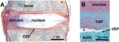
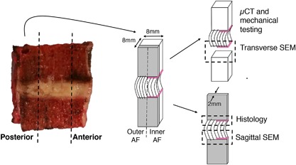
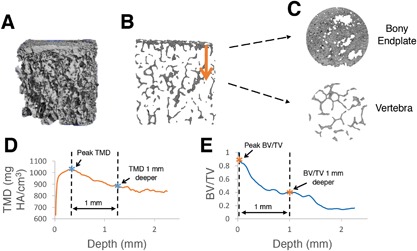
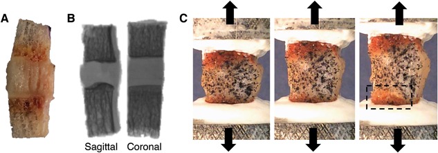
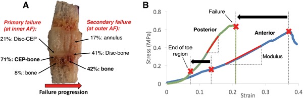
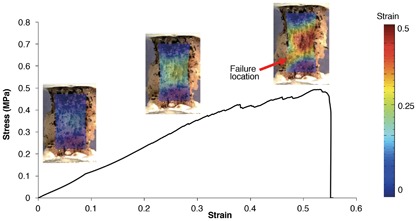
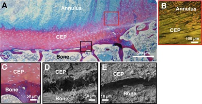
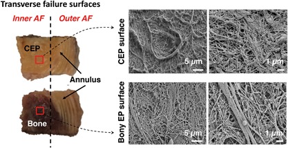
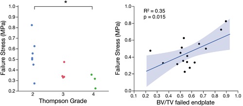
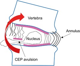
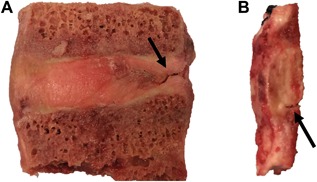
Damage at the intervertebral disc-vertebra interface associates with back pain and disc herniation. However, the structural and biomechanical properties of the disc-vertebra interface remain underexplored. We sought to measure mechanical properties and failure mechanisms, quantify architectural features, and assess structure-function relationships at this vulnerable location. Vertebra-disc-vertebra specimens from human cadaver thoracic spines were scanned with micro-computed tomography (μCT), surface speckle-coated, and loaded to failure in uniaxial tension. Digital image correlation (DIC) was used to calculate local surface strains. Failure surfaces were scanned using scanning electron microscopy (SEM), and adjacent sagittal slices were analyzed with histology and SEM. Seventy-one percent of specimens failed initially at the cartilage endplate-bone interface of the inner annulus region. Histology and SEM both indicated a lack of structural integration between the cartilage endplate (CEP) and bone. The interface failure strength was increased in samples with higher trabecular bone volume fraction in the vertebral endplates. Furthermore, failure strength decreased with degeneration, and in discs with thicker CEPs. Our findings indicate that poor structural connectivity between the CEP and vertebra may explain the structural weakness at this region, and provide insight into structural features that may contribute to risk for disc-vertebra interface injury. The disc-vertebra interface is the site of failure in the majority of herniation injuries. Here we show new structure-function relationships at this interface that may motivate the development of diagnostics, prevention strategies, and treatments to improve the prognosis for many low back pain patients with disc-vertebra interface injuries. © 2017 The Authors. Journal of Orthopaedic Research® Published by Wiley Periodicals, Inc. on behalf of Orthopaedic Research Society. J Orthop Res 36:192-201, 2018.

Keywords: avulsion; cartilage endplate junction; collagen; disc herniation; intervertebral disc.


Figures

Figure 1
Figure 1
Histologic sections from human cadaveric lumbar spines. (A) Tri‐chrome Mallory–Heidenhain stained section depicting the annulus fibrosus, nucleus pulposus, vertebral bone, and cartilage endplate (CEP). (B) Safranin‐O stained section illustrating an in situ CEP avulsion (at asterisk) from the underlying vertebral endplate (VEP).
Figure 2
Figure 2
Sample preparation and allocation. Bone‐disc‐bone specimens were cut from the posterior and anterior annulus regions to include both outer and inner annulus fibrosus (AF). A thin sagittal slice was cut for sagittal‐plane histology and SEM, while the bulk sample was scanned with μCT and mechanically tested. Failure surfaces were scanned with SEM. Note that annulus fibers of the outer AF attach directly to the vertebra, while those in the inner AF attach to the cartilage endplate (denoted by pink line).
Figure 3
Figure 3
Process of calculating gradients in tissue mineral density (TMD) and trabecular bone volume fraction (BV/TV) at the endplate junction regions. (A) Three‐dimensional μCT data is loaded into custom IDL algorithm, (B and C) algorithm traverses from the dense bony endplate into the deeper vertebral bone, and average values of (D) TMD, and (E) BV/TV are plotted by depth. Differences between peak values (first asterisk) and values 1 mm deeper (second asterisk) were used to assess local gradients in TMD and BV/TV. Note that (B) and (C) are slices in the sagittal and transverse planes, respectively.
Figure 4
Figure 4
Specimen is (A) cleaned of bone marrow, (B) X‐rayed in two orthogonal planes to calculate geometry, and (C) speckle‐coated on parasagittal surface, mounted in custom‐designed aluminum pots, and pulled in tension to failure. Box in (C) shows location of endplate junction failure. A, B (left), and C are all sagittal views with the inner annulus on the left and outer annulus on the right.
Figure 5
Figure 5
(A) Distribution of failure locations at inner annulus fibrosus (AF) and outer AF regions, with red arrow showing typical direction of failure progression from inner to outer AF. CEP, cartilage endplate; (B) Stress‐strain curves for representative posterior annulus and anterior annulus specimens. Posterior specimens had a shorter toe region and lower failure strain (denoted by black arrows) than anterior specimens, as well as a higher modulus than anterior specimens (p < 0.01). Strains on x‐axis are grip‐to‐grip strains along the loading axis.
Figure 6
Figure 6
Stress‐strain curve for a bone‐disc‐bone specimen. Strains on x‐axis are grip‐to‐grip strains along the loading axis. Principal strain maps are overlaid on specimen images acquired at corresponding levels of applied strain.
Figure 7
Figure 7
Sagittal histology (A,B,C) and SEM (D,E) images of the endplate junction. (A,C) are stained with trichrome stain, and (B) is stained with picrosirius red and visualized under polarized light. (B) shows annulus fibers integrating with the cartilage endplate (CEP), while (C) shows a clear demarcation between CEP and bone with no integration. (D and E) show small gap between CEP and bone using SEM. Black and red boxes on (A) are color‐coded to correspond with approximate regions of (B–E).
Figure 8
Figure 8
(Left) Transverse failure surfaces for specimen that failed at cartilage endplate (CEP)‐bone interface at inner annulus fibrosus (AF) region and failed in mid‐annulus at outer AF region. Red squares indicate location of SEM scans; (Right) SEM scans of failure surfaces imaged for CEP; and opposing bony endplate surface.
Figure 9
Figure 9
(Left) Failure stress was significantly lower in samples from discs with Thompson Grades 4 versus 2 (*p = 0.026, t‐test); (Right) Failure stress was positively correlated with trabecular bone volume fraction (BV/TV) in the vertebral endplate that failed during mechanical tests (R 2 = 0.35, p = 0.015).
Figure 10
Figure 10
One proposed mechanism of disc herniation, in which cartilage endplate (CEP) is avulsed from bone, allowing disc material to escape. Endplate junction failure is the most common cause of clinical disc herniations1 and may occur during spinal movements involving bending motions that place the CEP‐bone interface in tension.
Figure 11
Figure 11
Un‐tested lumbar specimens. Specimens are often too degenerated for mechanical testing and show (A) annular fissures and (B) separation at the CEP‐bone interface.

References

    1. Rajasekaran S, Bajaj N, Tubaki V, et al. 2013. ISSLS Prize winner: the anatomy of failure in lumbar disc herniation: an in vivo, multimodal, prospective study of 181 subjects. Spine (Phila Pa 1976) 38:1491–1500. - PubMed
    1. Lama P, Zehra U, Balkovec C, et al. 2014. Significance of cartilage endplate within herniated disc tissue. Eur Spine J 23:1869–1877. - PubMed
    1. Fields AJ, Liebenberg EC, Lotz JC. 2014. Innervation of pathologies in the lumbar vertebral end plate and intervertebral disc. Spine J 14:513–521. - PMC - PubMed
    1. Thompson KJ, Dagher AP, Eckel TS, et al. 2009. Modic changes on MR images as studied with provocative diskography: clinical relevance—a retrospective study of 2457 disks. Radiology 250:849–855. - PubMed
    1. Thomopoulos S, Williams GR, Gimbel J a, et al. 2003. Variation of biomechanical, structural, and compositional properties along the tendon to bone insertion site. J Orthop Res 21:413–419. - PubMed

Publication types