

A Capacitance-To-Digital Converter for MEMS Sensors for Smart Applications
- PMID: 28590425
- PMCID: PMC5492861
- DOI: 10.3390/s17061312
A Capacitance-To-Digital Converter for MEMS Sensors for Smart Applications
Abstract
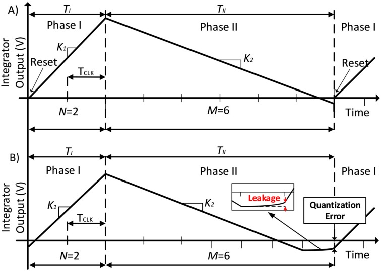
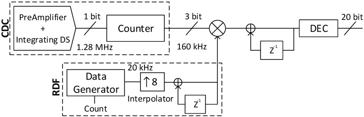
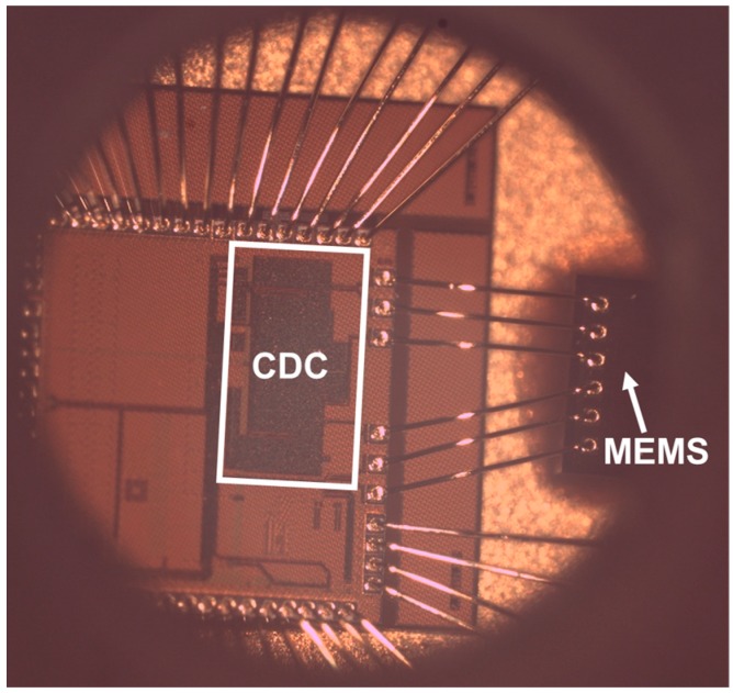
The use of MEMS sensors has been increasing in recent years. To cover all the applications, many different readout circuits are needed. To reduce the cost and time to market, a generic capacitance-to-digital converter (CDC) seems to be the logical next step. This work presents a configurable CDC designed for capacitive MEMS sensors. The sensor is built with a bridge of MEMS, where some of them function with pressure. Then, the capacitive to digital conversion is realized using two steps. First, a switched-capacitor (SC) preamplifier is used to make the capacitive to voltage (C-V) conversion. Second, a self-oscillated noise-shaping integrating dual-slope (DS) converter is used to digitize this magnitude. The proposed converter uses time instead of amplitude resolution to generate a multibit digital output stream. In addition it performs noise shaping of the quantization error to reduce measurement time. This article shows the effectiveness of this method by measurements performed on a prototype, designed and fabricated using standard 0.13 µm CMOS technology. Experimental measurements show that the CDC achieves a resolution of 17 bits, with an effective area of 0.317 mm², which means a pressure resolution of 1 Pa, while consuming 146 µA from a 1.5 V power supply.
Keywords: CDC; MEMS; capacitive sensors; dual-slope; low power; pressure sensor.
Conflict of interest statement
The authors declare no conflict of interest.
Figures


References
-
- Langfelder G., Buffa C., Frangi A., Tocchio A., Lasalandra E., Longoni A. Z-Axis Magnetometers for MEMS Inertial Measurement Units Using an Industrial Process. IEEE Trans. Ind. Electron. 2013;60:3983–3990. doi: 10.1109/TIE.2012.2210958. - DOI
-
- Xia S., Makinwa K., Nihtianov S. A capacitance-to-digital converter for displacement sensing with 17b resolution and 20μs conversion time; Proceedings of the International Solid-State Circuits Conference Digest of Technical Papers; San Francisco, CA, USA. 19–23 February 2012; pp. 198–200.
-
- Oh S., Jung W., Yang K., Blaauw D., Sylvester D. 15.4b incremental sigma-delta capacitance-to-digital converter with zoom-in 9b asynchronous SAR; Proceedings of the Symposium on VLSI Circuits Digest of Technical Papers; Honolulu, HI, USA. 10–13 June 2014; pp. 1–2.
-
- Tan Z., Chae Y., Daamen R., Humbert A., Ponomarev Y.V., Pertijs M.A.P. A 1.2V 8.3nJ energy-efficient CMOS humidity sensor for RFID applications; Proceedings of the Symposium on VLSI Circuits Digest of Technical Papers; Honolulu, HI, USA. 13–15 June 2012; pp. 24–25.
-
- Jung W., Jeong S., Oh S., Sylvester D., Blaauw D. 27.6 A 0.7pF-to-10nF fully digital capacitance-to-digital converter using iterative delay-chain discharge; Proceedings of the International Solid-State Circuits Conference Digest of Technical Papers; San Francisco, CA, USA. 22–26 February 2015; pp. 1–3. - PMC - PubMed
LinkOut - more resources
Full Text Sources
Other Literature Sources
