. 2017 Jun 7;146(21):214704.
doi: 10.1063/1.4984037.

Albumin (BSA) adsorption onto graphite stepped surfaces

Affiliations

Albumin (BSA) adsorption onto graphite stepped surfaces

Pamela Rubio-Pereda et al. J Chem Phys. .

Abstract

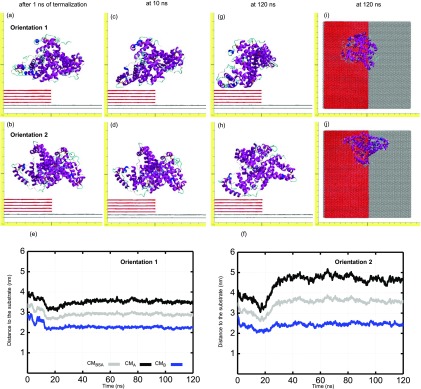
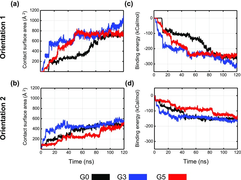
Nanomaterials are good candidates for the design of novel components with biomedical applications. For example, nano-patterned substrates may be used to immobilize protein molecules in order to integrate them in biosensing units. Here, we perform long MD simulations (up to 200 ns) using an explicit solvent and physiological ion concentrations to characterize the adsorption of bovine serum albumin (BSA) onto a nano-patterned graphite substrate. We have studied the effect of the orientation and step size on the protein adsorption and final conformation. Our results show that the protein is stable, with small changes in the protein secondary structure that are confined to the contact area and reveal the influence of nano-structuring on the spontaneous adsorption, protein-surface binding energies, and protein mobility. Although van der Waals (vdW) interactions play a dominant role, our simulations reveal the important role played by the hydrophobic lipid-binding sites of the BSA molecule in the adsorption process. The complex structure of these sites, that incorporate residues with different hydrophobic character, and their flexibility are crucial to understand the influence of the ion concentration and protein orientation in the different steps of the adsorption process. Our study provides useful information for the molecular engineering of components that require the immobilization of biomolecules and the preservation of their biological activity.


Figures

FIG. 1.
FIG. 1.
[(a)–(c)] A schematic view of graphite substrates: (a) G0: a flat surface constructed by three stacked graphene layers; (b) G3: a surface with a three graphene layer step height; and (c) G5: a surface with a five graphene layer step height. [(d)–(f)] Top and side views of the graphite substrates with the BSA molecule in orientation 1 (BSA-1): (d) G0; (e) G3; and (f) G5. In each case, the BSA center of mass (x and y coordinates) is located exactly above the geometrical center of the lowest graphene layer. The initial distance between the uppermost graphene layer and the BSA atom closest to the surface is 10 Å.
FIG. 2.
FIG. 2.
(a) The structure of the BSA molecule, showing the A and B fragments of the BSA molecule (colored in gray and blue, respectively) and the center of mass positions for the A (CMA) and B (CMB) fragments and for the whole molecule (CM). The positions of the hydrophobic lipid-binding pocket, located in fragment B, and the surrounding α-helices are highlighted with red cylinders. (b) The BSA molecule in adsorption orientation 1 (labeled BSA-1). (c) BSA molecule in adsorption orientation 2 (labeled BSA-2). BSA-2 can be obtained by rotating approximately 180° the BSA-1 configuration around an axis parallel to the graphene layers.
FIG. 3.
FIG. 3.
Top row: snapshots of BSA-1 orientation over G0 substrate taken (a) after initial energy optimization and 1 ns of MD thermalization; (c) after 10 ns of the MD simulation; (g) and (f) after 120 ns of the MD simulation in side and top views, respectively. Second row: snapshots of BSA-2 orientation over G0 substrate taken (b) after initial energy optimization and 1 ns of MD thermalization; (d) after 10 ns of the MD simulation; (h) and (j) after 120 ns of the MD simulation in side and top views, respectively. Third row: (e) and (f) evolution of BSA-1 and BSA-2, respectively, Z coordinate of the center of mass corresponding to the full molecule (gray line), the A fragment (black line), and the B fragment (blue line).
FIG. 4.
FIG. 4.
Top row: snapshots of BSA-1 orientation over G3 substrate taken (a) after initial energy optimization and 1 ns of MD thermalization; (c) after 10 ns of the MD simulation; (g) and (f) after 120 ns of the MD simulation in side and top views, respectively. Second row: snapshots of BSA-2 orientation over G3 substrate taken (b) after initial energy optimization and 1 ns of MD thermalization; (d) after 10 ns of the MD simulation; (h) and (j) after 120 ns of the MD simulation in side and top views, respectively. Third row: (e) and (f) evolution of BSA-1 and BSA-2, respectively, Z coordinate of the center of mass corresponding to the full molecule (gray line), the A fragment (black line), and the B fragment (blue line).
FIG. 5.
FIG. 5.
Top row: snapshots of BSA-1 orientation over G5 substrate taken (a) after initial energy optimization and 1 ns of MD thermalization; (c) after 10 ns of the MD simulation; (g) and (f) after 120 ns of the MD simulation in side and top views, respectively. Second row: snapshots of BSA-2 orientation over G5 substrate taken (b) after initial energy optimization and 1 ns of MD thermalization; (d) after 10 ns of the MD simulation; (h) and (j) after 120 ns of the MD simulation in side and top views, respectively. Third row: (e) and (f) evolution of BSA-1 and BSA-2, respectively, Z coordinate of the center of mass corresponding to the full molecule (gray line), the A fragment (black line), and the B fragment (blue line).
FIG. 6.
FIG. 6.
Time evolution, during the 120 ns of the MD simulation, of the contact surface area (CSA) as calculated from Eq. (1) (left column) and binding energies as calculated from Eq. (2) (right column), for the two orientations of the BSA molecule: BSA-1, top row, and BSA-2, bottom row. The G0, G3, and G5 graphite substrates were considered.
FIG. 7.
FIG. 7.
(a) Side and (b) front views of the BSA-1/G3 system after 200 ns of the MD simulation. (c) and (d) for the BSA-2/G3 system.
FIG. 8.
FIG. 8.
Square Displacement (SD) of the X, Y, and Z coordinates of the Center of Mass (CM) for both BSA orientations, BSA-1 (top row) and BSA-2 (bottom row) onto the G0, G3, and G5 graphite substrates.
FIG. 9.
FIG. 9.
Aminoacid distribution for the final protein adsorption configurations, as seen from the graphite surface, in the volume defined by the topmost graphene layer and an horizontal plane located 1 nm above it. The G0, G3, and G5 graphite substrates (columns) and the two BSA orientations (BSA-1, top row, BSA-2, bottom row) were considered. Negatively and positively charged residues are depicted in red and blue, respectively, while hydrophobic amino-acids are displayed in gray. Partial charges are assigned in accordance with the calculated ionization states of the titratable groups.
FIG. 10.
FIG. 10.
Hydrophobic and hydrophilic amino-acid residue distribution for the Sudlow sites (DSs) on the BSA-1 (top row) and BSA-2 (bottom row) orientations. On the left column, we represent their structure under pure water conditions (0 mM), and on the right column, we represent their structure at physiological conditions (140 mM). The right column images correspond to the protein structure right before the application of the forced adsorption protocol. Hydrophobic/hydrophilic amino-acid residues are colored in accordance with their hydrophobicity index: very hydrophilic, neutral, hydrophobic, and very hydrophobic residues are colored in red, orange, cyan, and dark blue, respectively. The DSs are highlighted by the green and yellow transparent surfaces. Under physiological conditions, the protein shields the strongly hydrophobic residue (in dark blue) at the bottom left while exposing the hydrophilic ones around it.

References

    1. Roy R. K. and Lee K. L., J. Biomed. Mater. Res., Part B 83B, 72 (2007).10.1002/jbm.b.30768 - DOI - PubMed
    1. Grill A., Diamond Relat. Mater. 12, 166 (2003).10.1016/s0925-9635(03)00018-9 - DOI
    1. Liu H. and Webster T. J., Biomaterials 28, 354 (2007).10.1016/j.biomaterials.2006.08.049 - DOI - PubMed
    1. Aoki R., Arakawa T., Misawa N., Tero R., Urisu T., Takeuchi A., and Ogino T., Surf. Sci. 601, 4915 (2007).10.1016/j.susc.2007.08.018 - DOI
    1. Roach P., Farrar D., and Perry C. C., J. Am. Chem. Soc. 127, 8168 (2005).10.1021/ja042898o - DOI - PubMed