Review
. 2018 Mar:168:71-87.
doi: 10.1016/j.neuroimage.2017.06.013. Epub 2017 Jun 7.

In vivo B0 field shimming methods for MRI at 7T

Affiliations
Review

In vivo B0 field shimming methods for MRI at 7T

Jason P Stockmann et al. Neuroimage. 2018 Mar.

Abstract

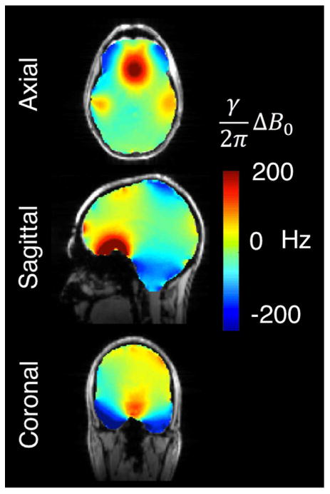
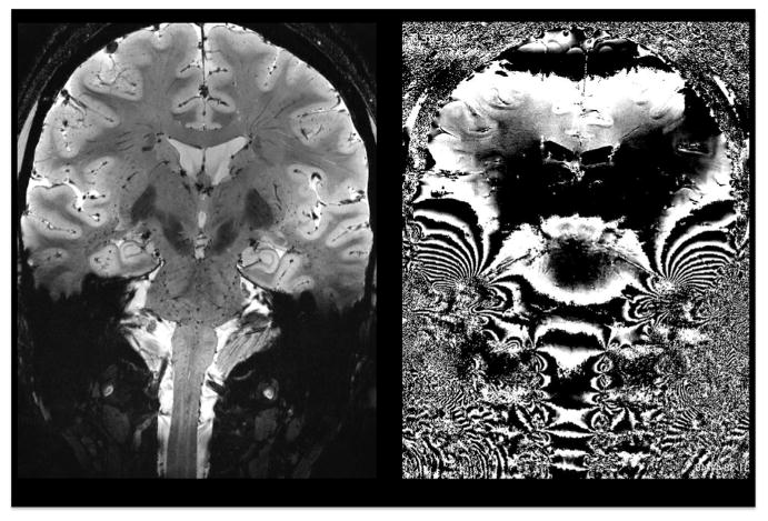
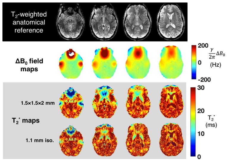
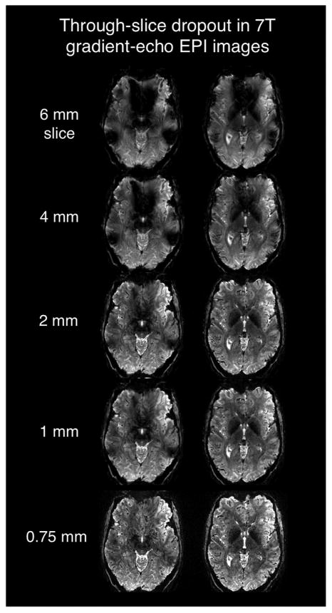
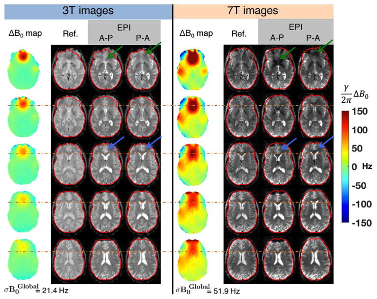
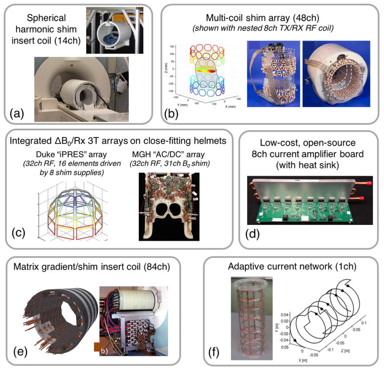
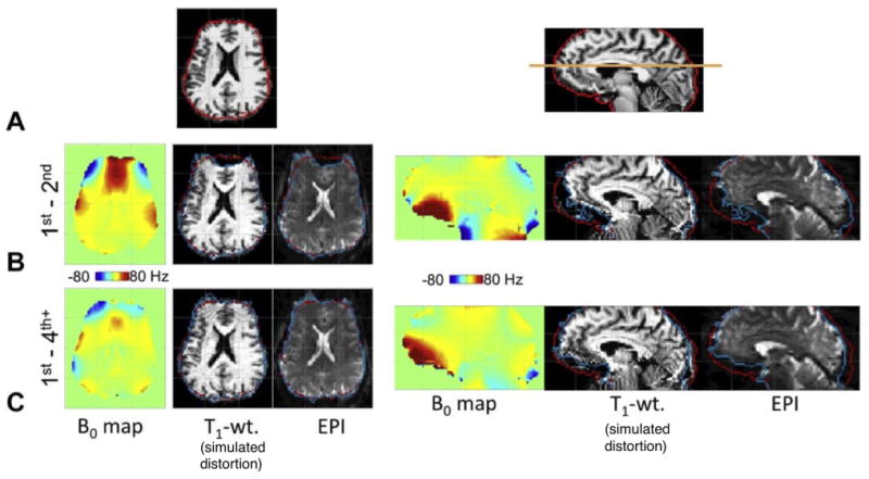
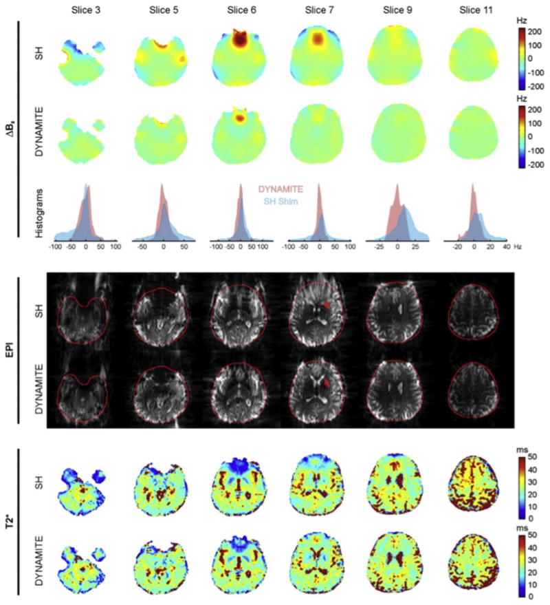
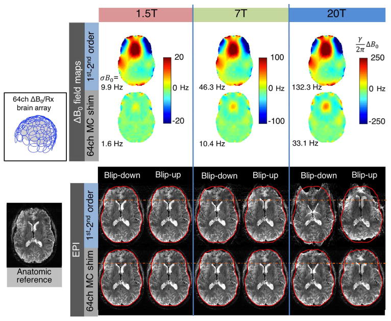
Functional MRI (fMRI) at 7T and above provides improved Signal-to-Noise Ratio and Contrast-to-Noise Ratio compared to 3T acquisitions. In addition to the beneficial effects on spin polarization and magnetization of deoxyhemoglobin, the increased applied field also further magnetizes air and tissue. While the magnets themselves typically provide a static B0 field with sufficient spatial homogeneity, the diamagnetism of tissue and the paramagnetism of air causes local field deviations inside the human head. These spatially-varying field offsets (ΔB0) cause image artifacts, especially in single shot EPI, including geometric distortion, signal dropout, and blurring. These effects are particularly strong near air-tissue interfaces such as the frontal sinus, and ear canals. Furthermore, if the field offsets are dynamically modulated through physiological processes such as respiration or motion, then the effect on the image time-series can be even more problematic. While post-processing methods have been developed to mitigate these effects, the ideal solution would be to reduce the ΔB0 variations at their source. Typically 7T scanners contain 2nd and some 3rd order spherical harmonic shim coil terms to cancel static ΔB0 variations of low spatial order. In this article, we will motivate the need for improved, higher-order compensation for B0 inhomogeneity and potentially add dynamic control of these fields. We discuss and compare several promising hardware approaches for static and dynamic B0 shimming using either higher-order spherical harmonic shim coils or multi-coil shim arrays as well as passive shimming approaches, and active variants such and adaptive current networks.

Keywords: B(0) shimming; Echo planar imaging; Functional MRI; In vivo off-resonance; Multi-coil shimming; Spherical harmonic shimming; T(2)(*) weighting.


Figures

Fig. 1
Fig. 1
Representative ΔB0 brain field map acquired at 7 T overlaid on a reference structural image. The FOV has been shimmed with 1st and 2nd order spherical harmonics on a 7 T Siemens scanner. The residual B0 inhomogeneity is particularly severe in regions bordering the sinuses, ear canals, and oral cavity, especially the orbitofrontal cortex, inferior temporal lobes, and brainstem. The standard deviation of ΔB0 within the masked region of the ΔB0 field map, σB0Global, is 51.9 Hz. Field maps are acquired using a two-echo gradient echo sequence with 2.4 × 2.4 mm in-plane resolution, 2 mm slices, and ΔTE = 1.02 ms.
Fig. 2
Fig. 2
Coronal T2*-weighted 7 T magnitude (left) and phase gradient echo images showing phase effects of severe spatial B0 variations. Both static and dynamic B0 variations in inferior brain areas pose a serious obstacle to structural and functional imaging. Data courtesy of Thomas Witzel, MGH.
Fig. 3
Fig. 3
ΔB0 and T2* maps from four representative slices of acquired at 7 T on a healthy volunteer. The macroscopic variation in B0 over each voxel makes it difficult to measure the underlying intrinsic tissue T2* value. The T2* maps are acquired at two different resolutions to illustrate the impact of voxel size on this problem. In regions of severe ΔB0, the mapped T2* values deviates substantially from the values exhibited by gray and white matter in regions with relatively homogeneous B0 distributions. T2* maps are calculated from gradient echo images acquired with the following range of TE values: [3.2, 17.3, 26.1, 32.7, 39.3, 46] ms. FOV = 210 × 183 mm. Resolution of acquired T2* maps: 1.5 mm in-plane with 2 mm slices; 1.1 mm isotropic.
Fig. 4
Fig. 4
Two slices in the inferior frontal lobes acquired with a T2* -weighted 7 T gradient echo 2D EPI sequence showing the relationship between slice thickness and signal dropout in regions of high ΔB0 (above the sinus and ear cavities.) The acquisition used conventional 1st–2nd order global B0 shimming. EPI parameters: TE/TR = 26/4000 ms, 0.75 × 0.75 mm in-plane, R = 4 GRAPPA acceleration, bandwidth = 1150 Hz, 0.24 effective echo spacing. Images courtesy of Jon Polimeni, MGH.
Fig. 5
Fig. 5
Five slices showing the ΔB0 field maps, undistorted T2-weighted gradient echo reference images, and co-registered EPI slices acquired on 3 T and 7 T after global 1st–2nd order shims have been applied. The EPI protocols use an identical echo spacing (0.56 ms), resolution (2 mm isotropic), readout bandwidth, and GRAPPA factor (R = 2). The TE was 30 ms at 3 T and 23 ms at 7 T. The EPI images were acquired with phase encoding running both anterior-posterior (A-P) and posterior-anterior (P-A) to more clearly depict the increased geometric distortion present in the 7 T images. For a given echo spacing, voxel shift scales linearly with ΔB0, resulting in distortion especially in the frontal lobe above the sinuses at 7 T. The outline of the cortical surface from the undistorted reference image is shown in red. The orange dotted line shows the position of the anterior tip of the lateral ventricles in the undistorted image, showing increased displacement in the 7 T EPI. The blue arrows highlight the same effect for anterior cingulate cortex. Signal voids due to through-slice dephasing are also more severe within B0 hotspots at 7 T, especially in the frontal lobe for slices close to the sinuses (green arrows) and above the ear canals. ΔB0 field maps are acquired with 2.4 × 2.4 mm in-plane resolution and 2 mm slices.
Fig. 6
Fig. 6
Photographs and diagrams of hardware systems that have been proposed for active, high-spatial order B0 shimming. (a) High Order Spherical Harmonic shimming system for 7 T MRI with 14 SH channels (up to 5th order) (photos courtesy of Piotr Starewicz of Resonance Research, Inc. and Assaf Tal of the Weizmann Institute). (b) 48ch 7 T multi-coil shim array made with four rings of 100-turn, 4.7 cm diameter shim coils arranged on a elliptic cylinder with a gap to accommodate the RF coils (Juchem et al., 2011a). (c) “iPRES” (Truong et al., 2014) or “AC/DC” (Stockmann et al., 2016a) integrated ΔB0/Rx coil arrays. These elements use the same conducting loops for RF receive and B0 shimming on close-fitting helmets (3 T designs shown). (d) Open-source, low-cost current amplifier designed to drive shim coils. (e) 84ch matrix gradient insert coil designed for both spatial encoding and high-order B0 shimming (Jia et al., 2016). (f) Adaptive current network using 14 MOSFET switches to route current along a grid on a cylindrical surface for tailored B0 shimming (Harris et al., 2014).
Fig. 7
Fig. 7
Figure reproduced with permission from Kim et al., (2016). 7 T ΔB0 field maps, undistorted anatomical T1 images, simulated distortions and EPI acquisitions for global spherical harmonic (SH) shimming. Results for 1st–2nd order terms are compared to 1st–4th order terms achieved using a dedicated high-order SH shim insert coil. Row A: Undistorted reference images for the representative axial and sagittal slices used for the comparison. Row B: results with 1st–2nd order shims applied. Row C: Results with 1st–4th order shims applied. The use of 3rd–4th order shim terms reduces σB0Global by 25% and corrects a significant fraction of the EPI geometric distortion, especially in the prefrontal cortex, bringing the cortical surface into closer alignment with its expected position (the red outline). The EPI acquisition used 2 mm iso. resolution and 0.75 ms echo spacing with no in-plane acceleration.
Fig. 8
Fig. 8
Reproduced with permission from Juchem et al. (2011). Data from 6 brain slices comparing experimental 1st–3rd order global SH shimming with 48ch single slice optimized dynamic MC shimming using the array shown in Fig. 6b. For each of the two shim methods, ΔB0 field maps, voxel ΔB0 histograms, multi-shot EPI images, and T2* maps are shown. Global SH shimming removes smoothly-varying components of B0, but provides limited improvement in areas with steep B0 variation such as the frontal lobes. Dynamic MC shimming helps mitigates these areas of peak ΔB0 and reduces geometric distortion both inside the brain (red arrow) and at the brain surface. Signal voids caused by through-slice dephasing are also mitigated. After MC shimming, the T2* distributions more closely match the values expected for the underlying tissue types (especially in the frontal lobe region of slice 7). The MC shim currents were updated in 1.5 ms and no artifacts were observed due to eddy currents or other transient effects. Across 5 human subjects, the average reported σB0Global values were 32.3 Hz for the global 1st–3rd order shims and 13.3 Hz for the dynamic MC shims, a 59% difference.
Fig. 9
Fig. 9
Reproduced with permission from Stockmann et al. (2016a). Demonstration of static slice-optimized B0 shimming performed at 3 T with the integrated 32ch ΔB0/Rx array coil described in Stockmann et al. (2016a) and shown in Fig. 6c. Three representative slices are compared for conventional global 2nd order shims and for global 2nd order + slice optimized MC shims. The data shown include ΔB0 field maps, undistorted anatomic images, and 1 mm EPI acquired with both anterior-posterior and posterior-anterior and anterior-posterior phase encoding directions and with echo spacing = 1.11 ms and no in-plane GRAPPA acceleration to exaggerate the distortion. The predicted and acquired ΔB0 field maps agree relatively well. MC shimming reduces the standard deviation of ΔB0 in each slice, σB0Local, by up to 55%. The orange line shows reduced distortion with MC shimming at the anterior aspect of the lateral ventricles. EPI parameters: 1 mm in-plane, 2 mm slice thickness, TE/TR = 65/18,940 ms, 6/8 partial Fourier, readout bandwidth 1190 Hz/pixel.
Fig. 10
Fig. 10
Early B0 shim results and EPI distortion correction using a prototype 7 T 31ch ΔB0/Rx array built on a close-fitting helmet. (a) Photograph of the top and bottom halves of the coil showing 6 ΔB0 shim-only loops added over the face for targeted shimming of the frontal lobes. (b) In vivo ΔB0 field maps shown in the three cardinal planes acquired with global 2nd-order shimming, global multi-coil (MC) shimming, and dynamic MC shimming. (c) A representative EPI slice acquired for the three shimming cases. Both posterior-anterior and anterior-posterior phase encoding directions are used to emphasize geometric distortion. The slice-optimized MC shims significantly reduce distortion in unaccelerated EPI images, bringing features such as the anterior tip of the lateral ventricles into closer alignment with an undistorted anatomic image (orange dotted lines). Shim currents were constrained to 2.5 A per channel and 20 A total. EPI parameters: 200 × 200 mm in-plane FOV, 1.1 mm in-plane, 2 mm slice, GRAPPA R = 3, echo spacing 0.81 ms (espeff = 0.27 ms), 7/8 partial Fourier, BW = 1544 Hz/pix, TE = 26 ms, TR = 2710 ms, flip angle = 90°. The contrast-matched reference image uses a 1 mm in-plane gradient echo acquisition.
Fig. 11
Fig. 11
Simulated B0 shimming for multiple high order shim configurations tested on an acquired 7 T brain ΔB0 field maps. We assess 2nd through 6th order SH terms along with 7 multi-coil (MC) shim geometries are shown in two representatives slices. Global shimming, slice optimized shimming and optimization of 2 slices for Simultaneous MultiSlice (SMS) acquisitions are compared. The baseline 1st–2nd order SH global shim is shown in the orange box. For both SH and MC shimming, slice-optimized shimming performs better than global shimming, as expected. However, for almost all of the coils, MB-2 shim performance is nearly as good as slice-optimized shimming, demonstrating the flexibility of the high-spatial order shim basis sets to simultaneously shim two slices separated by a gap. The constrained optimization for the MC setups used maximum current amplitudes of 3 A/ch and 50 A/total.
Fig. 12
Fig. 12
Simulated shim performance for the high order shim hardware configurations shown in Fig. 11. (a) Set of seven brain 7 T ΔB0 field maps acquired on healthy volunteers that were used in the simulations. Results for the ΔB0 field map boxed in blue are shown in Fig. 11. (b) Diagram of the four shim strategies simulated: global, MB-2, MB-3, and single slice-optimized. (c) Bar graph showing the 95%, 90%, and 80% residuals as well as σB0Global for simulated shimming over all field maps (error bars reported in Table 2). Global, MB-2, MB-3, and slice-optimized results are reported from left-to-right in the bar cluster for each shimming system. As expected, slice-optimized shimming performs better than global shimming, since it requires fewer degrees of freedom to shim a single slice as compared to a whole brain. For both SH and MC shims, dynamic shim updating significantly improves σB0Global and the residuals for SMS acquisitions as compared to global shimming. While shim performance degrades as the number of SMS slices increases, both MB-2 and MB-3 still substantially outperform global shimming. The biggest improvement over baseline global 2nd order shimming (orange box) was provided by slice-optimized 6th order SH shims and 48ch cyl. MC shims (∼ 60% reduction in σB0Global).
Fig. 13
Fig. 13
ΔB0 field maps and simulated EPI distortion for 1.5 T, 7 T, and 20 T brain imaging. The 1.5 T and 20 T ΔB0 field maps are scaled versions of an acquired 7 T brain field map. Two cases are shown: global 1st–2nd order SH shimming and global 1st–2nd order SH shimming+slice-optimized 64ch MC shimming using the close-fitting ΔB0/Rx helmet coil configuration shown in Fig. 11. Geometric distortion is applied to a T2*-weighted anatomic reference image using FSL FUGUE for an echo spacing of 0.56 ms with GRAPPA acceleration of R = 2 (effective echo spacing of 0.28). Both anterior-posterior and posterior-anterior distortions are simulated to emphasize the distortion. ΔB0 and EPI voxel shifts scale linearly with field strength. While negligible at 1.5 T, the distortion becomes pronounced at 7 T, and at 20 T the images are cartoonishly warped. The voxel shifts are 13 times larger at 20 T than at 1.5 T. The 64ch multi-coil shim array is capable of reducing the distortion to less than what occurs at 7 T with global 2nd order shimming (σB0 within the slice is 33.1 Hz for 20 T MC shim versus 46.3 Hz for 7 T 1st–2nd order SH shim). This highlights the need for high-spatial order shimming systems to enable functional MR imaging on envisioned scanners of the future with field strengths well above 7 T.

References

    1. Adalsteinsson E, Conolly SM, Xu H, Spielman DM. Design of dedicated shim fields. Proc Int Soc Magn Res Med. 1999:477.
    1. Andersson JLR, Skare S, Ashburner J. How to correct susceptibility distortions in spin-echo echo-planar images: application to diffusion tensor imaging. Neuroimage. 2003;20:870–888. http://dx.doi.org/10.1016/S1053-8119(03)00336-7. - DOI - PubMed
    1. Arango N, Stockmann JP, Witzel T, Wald L, White J. Open-source, low-cost, flexible, current feedback-controlled driver circuit for local B0 shim coils and other applications. Int Soc Magn Res Med. 2016:1157.
    1. Arango N, Stockmann JP, White J, Wald LL. Open source, low-cost currrent driver board for MRI research. 2016 〈 http://rflab.martinos.org/index.php/Current_driver:Current_driver〉.
    1. Barmet C, De Zanche N, Pruessmann KP. Spatiotemporal magnetic field monitoring for MR. Magn Reson Med. 2008;60:187–197. http://dx.doi.org/10.1002/mrm.21603. - DOI - PubMed

Publication types

MeSH terms