. 2017 Jun 6:5:e3427.
doi: 10.7717/peerj.3427. eCollection 2017.

A methodology of theropod print replication utilising the pedal reconstruction of Australovenator and a simulated paleo-sediment

Affiliations

A methodology of theropod print replication utilising the pedal reconstruction of Australovenator and a simulated paleo-sediment

Matt A White et al. PeerJ. .

Abstract

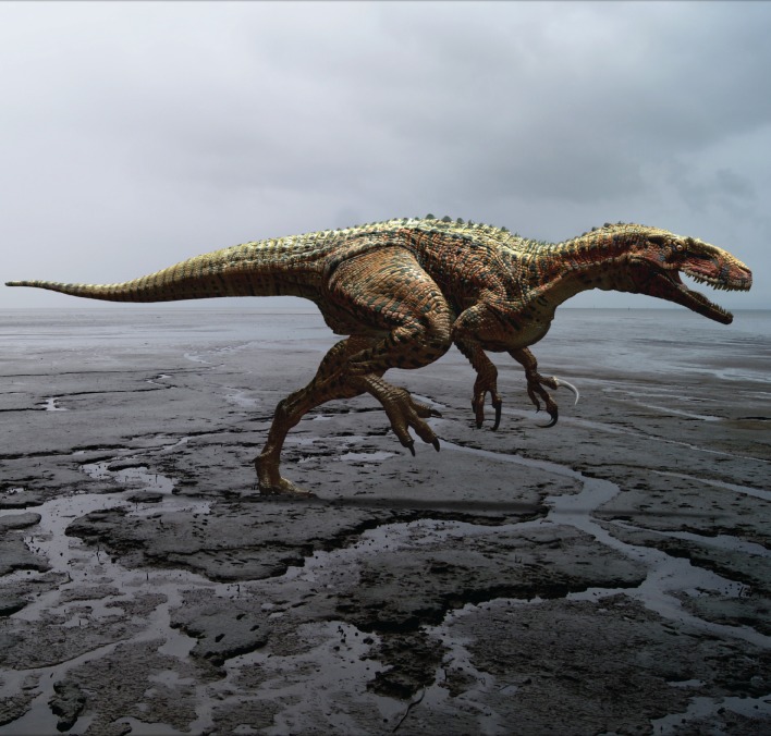
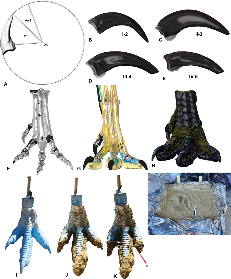
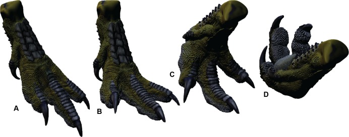
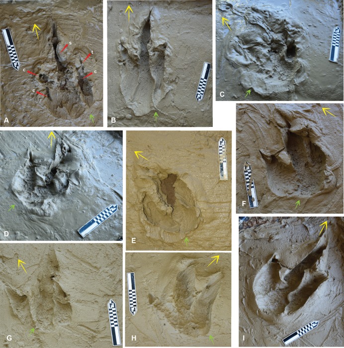
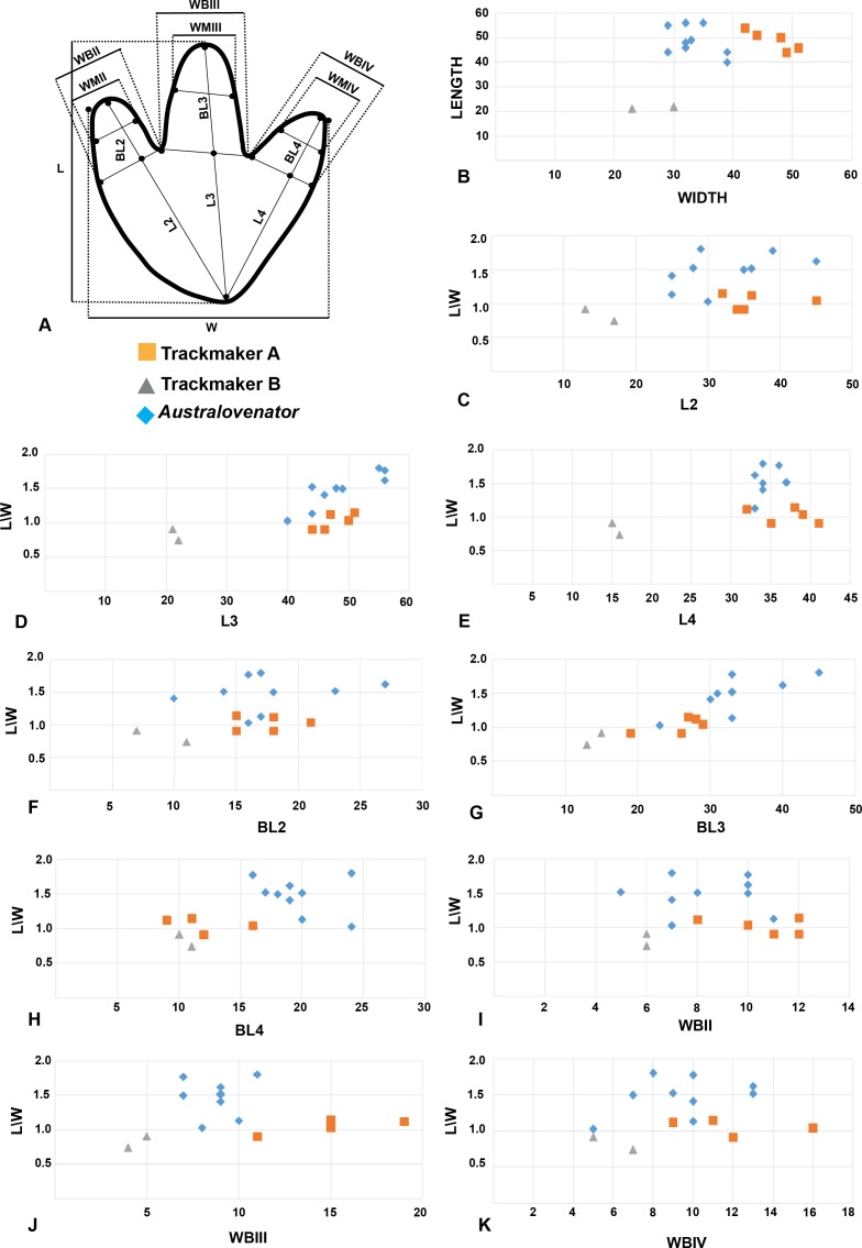
Distinguishing the difference between theropod and ornithopod footprints has proved a difficult task due to their similarities. Herein our aim was to produce a method where a skeleton could be more closely matched to actual fossilised footprints. The reconstructed pes of the Australian Megaraptoran Australovenator wintonensis was utilised for this footprint reconstruction. It was 3-D printed in life size, molded and cast to produce a flexible theropod foot for footprint creation. The Dinosaur Stampede National Monument, Lark Quarry, Queensland, Australia was used as our case study to compare fossilised dinosaur footprints with our reconstructed theropod prints. The footprints were created in a sediment that resembled the paleo-sediments of Lark Quarry prior to being traversed by dinosaurs. Measurements of our Australovenator prints with two distinctly different print types at Lark Quarry revealed similarities with one distinct trackway which has been the center of recent debate. These footprints consist of 11 consecutive footprints and show distinct similarities in both size and proportions to our Australovenator footprints.

Keywords: Australovenator; Lark Quarry; Megaraptorid; Theropod; Trackway.


Conflict of interest statement

The authors declare there are no competing interests.

Figures

Figure 1
Figure 1. Reconstruction of Australovenator wintonensis.
Artwork by Travis R. Tischler.
Figure 2
Figure 2. Creation of a theropod print for a comparison with the prints at Lark Quarry using a reconstructed pes of Australovenator.
(A) Calculating the estimated sheath extent using pedal phalanx IV-5 as an example; (B) Pedal phalanx I-2 with reconstructed sheath; (C) Pedal phalanx II-3 with reconstructed sheath; (D) Pedal phalanx III-4 with reconstructed sheath; (E) Pedal phalanx IV-5 with reconstructed sheath; (F) Reconstructed pes; (G) Biologically reconstructed pes; (H) Skin covered biologically restored pes; (I) Cast of 3-D printed pes using flexible resin; (J) Clay covering the base of the cast foot synthesizing a pes that had already traversed the mud prior to making a subsequent print; (K) The addition of an elastic band to simulate the pes in touch-down articulation; (L) The foot print box used to replicate theropod footprints in various motions and mud at varying saturations.
Figure 3
Figure 3. Range of motion of the Australovenator pes.
(A) Touch-down phase; (B) Weight-bearing phase; (C) Kick-off phase; (D) Suspended phase following kick-off.
Figure 4
Figure 4. The Australovenator prints that were measured and compared with prints from the DSNM Lark Quarry.
Symbols: small arrow entry direction; large arrow exit direction. (A) Pes forward motion; (B) Pes forward motion with heel slide; (C) Pes entered substrate at a slight angle favoring the medial side with digit IV entering substrate first, followed by full weight bearing phase, slight rotation and exiting substrate veering left; (D) Pes entered substrate at slight angle favoring the lateral side with digit IV entering substrate first, followed by full weight bearing phase, slight rotation and exiting substrate veering left, with sediment bulging up on the medial side of the heel; (E) Pes entered substrate in forward motion with digit V contacting substrate first followed by full weight bearing phase and then was rotated in situ simulating a direction change veering left; (F) Pes entered substrate at a slight angle favoring the lateral side with digit IV entering substrate first, followed by full weight bearing phase, slight rotation and exiting substrate veering left, with sediment bulging up on the medial side of the heel; (G) Pes entered substrate at a slight angle favoring the lateral side with digit IV entering substrate first, the heel did not contact the sediment and the pes exited the substrate veering left; (H) Pes entered substrate at a slight angle favoring the medial side with digit II making first contact with the substrate, the heel did not contact the sediment as the pes exited the substrate veering right, which resulted in a shallow digit IV impression; (I) Pes entered substrate in a forward motion followed by full weight bearing phase and exited the substrate in the same direction. Abbreviations: claw (c); slumping (s); tunnel (t).
Figure 5
Figure 5. Trace features created by the Australovenator flexible foot prop.
(A) Left Australovenator print displaying entry striation grooves (B) and skin impressions created from the papillae from the base of the foot (C); (B) close-up of the parallel grooves created from the Australovenator foot entering the sediment; (C) Close-up of the digital pad impression formed by the rounded papillae; (D) Fossilised Triassic theropod prints with parallel striation grooves (adopted from Fig. 1D in Gatesy, 2001); (E) Fossilised Triassic theropod prints with pad impressions displaying hexagonally arranged dimples (adopted from Fig. 1A in Gatesy, 2001); (F) Australovenator print displaying entry striation grooves and curved striations created from the papillae as the pes twisting in the sediment to initial a change in direction; (G) Outline of striations draw from (F); (H) Close up of striations in (F).
Figure 6
Figure 6. Comparing Trackmaker A prints of Lark Quarry with the Australovenator prints to help identify various morphological features of the Lark Quarry prints.
(A) Trackmaker A LQ6 (right) a digitigrade print slightly favoring the lateral side; (B) Trace of morphological features and print outline of LQ6; (C) Graphic depicting the movement of the Australovenator foot (left foot) used to create (D); (D) Australovenator print simulated by favoring the medial side which resulted in digits II and III to be slightly deeper than digit IV, similar to LQ6; (E) Trackmaker A LQ8 (right) a digitigrade print with a distinct claw trace of digit II and a slight claw trace of digit IV; (F) Trace of morphological features and print outline of LQ8; (G) Graphic depicting the movement of the Australovenator foot used to create (H); (H) Australovenator digitigrade print which resulted in some minor tunneling of the digits before they were manually flicked backward creating claw traces; (I) Trackmaker A LQ9 (left) a shallow digitigrade print; (J) Trace of morphological features and print outline of LQ9; (K) Graphic depicting the movement of the Australovenator foot used to create (L); (L) Australovenator digitigrade print with digit tunneling, which if they collapsed, would make the print similar to LQ9; The sediment was slightly drier than the sediment used to create (D) which created more sediment suction, resulting in pronounced hexagonal like papillae traces; (M) Trackmaker A LQ10 (right) digitigrade print with slight digit tunneling and claw traces of each digit; (N) Trace of morphological features and print outline of LQ10; (O) Graphic depicting the movement of the Australovenator foot used to create (P); (Q) Australovenator digitigrade print with minor digit tunneling and kick-off claw traces similar to LQ10. Abbreviations: claw trace (c), suction of substrate to the foot causing suction trace (s), tunnel features of the digits (t). Arrows depict direction of movement.
Figure 7
Figure 7. Comparing Trackmaker A prints of Lark Quarry with the Australovenator prints to help identify various morphological features of the Lark Quarry prints.
(A) Trackmaker A LQ1 (left foot), with a distinct claw trace of digit II; (B) Trace of morphological features and print outline of LQ1; (C) Graphic depicting the movement of the Australovenator foot used to create (D); (D) Australovenator print with a full heel contact similar to LQ1; (E) Trackmaker A LQ3 (left foot) is the longest print of this trackway; (F) Trace of morphological features and print outline of LQ3; (G) Graphic depicting the movement of the Australovenator foot used to create (H); (H) Australovenator print with a slight heel slide creating a slightly longer print similar to LQ3; (I) Trackmaker A LQ4 (right foot) has been restored in situ around the heel region and digit IV giving the heel a rounded appearance; (J) Trace of morphological features and print outline of LQ4; (K) Graphic depicting the movement of the Australovenator foot used to create (L); (L) Australovenator print with full heel contact, favoring the lateral side creating a wider fourth digit impression, which formed a rounded heel impression (generally regarded as characteristic of ornithopod prints) which is similar to LQ4; (M) Trackmaker A LQ5 (left foot) favored the medial side when entered into the substrate with an exaggerated heel slide. Some claw traces following kick-off are also visible; (N) Trace of morphological features and print outline of LQ5; (O) Graphic depicting the movement of the Australovenator foot used to create (P); (P) Australovenator print favoring the lateral side with full heel contact and slight rotation to simulate direction change. Abbreviations: claw trace (c), suction of substrate to the foot causing suction trace (s), tunnel features of the digits (t). Arrows depict direction of movement.
Figure 8
Figure 8. Two consecutive prints from Trackmaker B (ornithopod) from DSNM Lark Quarry.
(A) Print 3 (left); (B) Trace of print 3; (C) Print 4 (right); (D) Trace of print 4.
Figure 9
Figure 9. Bivariate plots comparing the print proportions of Trackmaker A, Trackmaker B and Australovenator.
(A) Measurement diagram; (B) Length against Width; (C) (L/W) against (L2); (D) (L/W) against (L3); (E) (L/W) against (L4); (F) (L/W) against (BL2); (G) (L/W) against (BL3); (H) (L/W) against (BL4); (I) (L/W) against (WBII); (J) (L/W) against (WBIII); (K) (L/W) against (WBIV).

References

    1. Cuesta E, Diaz-Martinez I, Ortega F, Sanz JL. Did all theropods have chicken-like feet? First evidence of a non-avian dinosaur podotheca. Cretaceous Research. 2015;56:53–59. doi: 10.1016/j.cretres.2015.03.008. - DOI
    1. Falkingham PL. Interpreting ecology and behaviour from the vertebrate fossil track record. Journal of Zoology. 2014;292(4):222–228. doi: 10.1111/jzo.12110. - DOI
    1. Falkingham PL. Applying objective methods to subjective track outlines. In: Falkingham PL, Daniel M, Richter A, editors. Dinosaur tracks the next steps. Bloomington: Indiana University Press; 2016. pp. 72–80.
    1. Falkingham PL, Gatesy SM. The birth of a dinosaur footprint: subsurface 3D motion reconstruction and discrete element simulation reveal track ontogeny. Proceedings of the National Academy of Sciences United States of America. 2014;111:18279–18284. doi: 10.1073/pnas.1416252111. - DOI - PMC - PubMed
    1. Gatesy SM. Skin impressions of Triassic theropods as records of foot movement. Bulletin of the Museum of Comparative Zoology. 2001;156(1):137–149.

LinkOut - more resources