Review
. 2017 Jun;13(2):100-111.
doi: 10.1183/20734735.004717.

Novel approaches to ultrasonography of the lung and pleural space: where are we now?

Affiliations
Review

Novel approaches to ultrasonography of the lung and pleural space: where are we now?

Daniel Lichtenstein. Breathe (Sheff). 2017 Jun.

Abstract

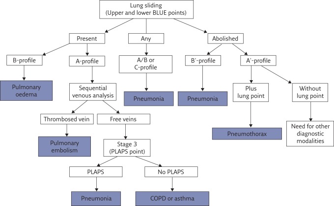
This review article is an update of what should be known for practicing basic lung ultrasound in the critically ill (LUCI) and is also of interest for less critical disciplines (e.g. pulmonology). It pinpoints on the necessity of a professional machine (not necessarily a sophisticated one) and probe. It lists the 10 main signs of LUCI and some of the main protocols made possible using LUCI: the BLUE protocol for a respiratory failure, the FALLS protocol for a circulatory failure, the SESAME protocol for a cardiac arrest and the investigation of a ventilated acute respiratory distress syndrome patient, etc. It shows how the field has been fully standardised to avoid confusion.

Key points: A simple ultrasonography unit is fully adequate, with minimal filters, and provides a unique probe for integrating the lung into a holistic, whole-body approach to the critically ill.Interstitial syndrome is strictly defined. Its clinical relevance in the critically ill is standardised for defining haemodynamic pulmonary oedema, pneumonia and pulmonary embolism.Pneumothorax is strictly and sequentially defined by the A'-profile (at the anterior wall in a supine or semirecumbent patient, abolished lung siding plus the A-line sign) and then the lung point.The BLUE protocol integrates lung and venous ultrasound findings for expediting the diagnosis of acute respiratory failure, following pathophysiology, allowing prompt diagnosis of pneumonia, haemodynamic pulmonary oedema, exacerbated chronic obstructive pulmonary disease or asthma, pulmonary embolism or pneumothorax, even in clinically challenging presentations.

Educational aims: To understand that the use of lung ultrasound, although long standardised, still needs educational efforts for its best use, a suitable machine, a suitable universal probe and an appropriate culture.To be able to use a terminology that has been fully standardised to avoid any confusion of useless wording.To understand the logic of the BLUE points, three points of interest enabling expedition of a lung ultrasound examination in acute respiratory failure.To be able to cite, in the correct hierarchy, the seven criteria of the B-line, then those of interstitial syndrome.To understand the sequential thinking when making ultrasound diagnosis of pneumothorax.To be able to use the BLUE protocol for building profiles of pneumonia (or acute respiratory distress syndrome) and understand their limitations.To understand that lung ultrasound can be used for the direct analysis of an acute respiratory failure (the BLUE protocol), an acute circulatory failure (the FALLS protocol) and even a cardiac arrest (SESAME protocol), following a pathophysiological approach.To understand that the first sequential target in the SESAME protocol (search first for pneumothorax in cardiac arrest) can also be used in countless more quiet settings of countless disciplines, making lung ultrasound in the critically ill cost-, time- and radiation-saving.To be able to perform a BLUE protocol in challenging patients, understanding how the best lung ultrasound can be obtained from bariatric or agitated, dyspnoeic patients.


Conflict of interest statement

Conflict of interest None declared.

Figures

Figure 1
Figure 1
The BLUE points. The BLUE points respect LUCI principles 3 and 7. They have been made simple for expediting protocols without loss of information. a) The upper BLUE hand (here the hand of the operator, who has checked that the patient’s hand is approximately the same size; if not, rough adaptations are performed) is applied just below the clavicle and parallel to it, the tips of fingers touching the midline. The upper BLUE point is defined at the middle of the upper BLUE hand. The lower BLUE hand is applied just below. The lower BLUE point is defined at the middle of the palm of the lower BLUE hand. The heart is usually avoided using this way. The lung usually stops at the lower finger. b) The PLAPS point is defined by drawing a transverse line from the lower BLUE point until the posterior axillar line is reached (or better, as posterior as possible). Note that the insertion of the probe between the (supine, ventilated) patient and bed sometimes makes perfect acquisition difficult but this makes the posterior lung of such patients accessible to ultrasound.
Figure 2
Figure 2
The A-profile. This single figure shows multiple data. The bat sign appears in the left image. The upper and lower ribs (black arrows) indicate the location of the pleural line (upper white arrows), which must be 0.5 cm (in adults) below the rib line. This works in extreme conditions (major dyspnoea, agitation, etc.). The pleural line always indicates the parietal pleura but indicates the visceral pleura only when joined. Merlin’s space defines the area located between the pleural line, the shadow of the ribs and the bottom of the image. The A-line (lower white arrows) is the repetition of the pleural line at a standardised distance, the skin–pleural line distance. The A-line indicates gas below the pleural line. The seashore sign: on the right image, one can see an upper rectangle (called Keye’s space) with a stratified pattern and a lower rectangle with a sandy pattern (the M-mode of Merlin’s space) both separated exactly by the pleural line (continuation of the white arrows from the left image). Note that with intelligent technology, both images are not only aligned but, mostly, exactly aligned, unlike on many modern machines. The seashore sign demonstrates lung sliding. We can see that lung sliding arises strictly from the pleural line, not 1 mm above or below. The A-profile is the anterior association of both images, i.e. A-lines plus lung sliding. The A-profile indicates a pulmonary artery occlusion pressure <18 mmHg, a basic datum in a circulatory failure (FALLS protocol).
Figure 3
Figure 3
Pleural effusion. Longitudinal scan at the PLAPS point. The pleural effusion is defined not because of (as shown here) a hypoechoic tone but by the appearance of the lung line (lower white arrows), which indicates the visceral pleura. The pleural line, which is clearly visible (upper white arrows) indicates here only the parietal pleura. All effusions, anechoic or echoic, can be diagnosed using the lung line. The volume of this effusion can be measured using a simple index. Note the underlying nontranslobar lung consolidation (subpleural, of course) with the shred sign (black arrows). The quad sign just describes the rough trapezium defined by the pleural line, the shadow of the ribs and the lung line. This is a typical example of (mixed) PLAPS.
Figure 4
Figure 4
Nontranslobar lung consolidation. Longitudinal scan at the PLAPS point. No lung line is present, i.e. there is no pleural effusion. A tissue-like image with a mostly fractal, deep boundary with the aerated underlying lung, the shred sign (or fractal sign), makes the diagnosis of a nontranslobar lung consolidation (which is, of course, subpleural). This is an example of PLAPS. If found anteriorly, this would be an example of the C-profile. Black arrows: fractal line. White arrows: ribs.
Figure 5
Figure 5
Translobar lung consolidation. This is another example of PLAPS. Four points can be described here. First, in this longitudinal view at the PLAPS point, there is a huge, whole lower left lobe consolidation (subpleural, of course). Novice users often see here “a lung”, unaware that the normally aerated lung cannot be seen this anatomical way, so this sign may be called, simply, the “lung sign”. It indicates translobar consolidation. The deep border is rectilinear, not shredded: the mediastinal pleura. Second, no air bronchogram is visible: air bronchograms are not needed for the diagnosis (dynamic air bronchograms would allow consideration that this consolidation is not retractile, among several signs). Third, this consolidation is homogeneous (abscesses and necrosis can generate hypoechoic areas) and has no loss of volume: the spleen (S) is in the normal place, another sign that would demonstrate the nonretractile origin of this consolidation. Fourth, this image comes from an ADR-4000, a portable unit from 1982, which we used to describe all of the signatures of lung ultrasound (which shows that the modern machines, especially the laptop units, were not necessary for the birth of bedside lung ultrasound). The diaphragm can be seen between the lung and spleen.
Figure 6
Figure 6
Interstitial syndrome and lung rockets. This figure presents most of the criteria of the B-line (the elementary sign). The B-line is defined using seven criteria, three of which are always present: a comet-tail artefact; arising from the pleural line; moving in concert with lung sliding (when lung sliding is present). The other four criteria are almost always present: long; well-defined; erasing A-lines; hyperechoic. This definition works in all situations and avoids confusion with other comet-tail artefacts that are not B-lines. The resulting sign, lung rockets, indicates that more than two B-lines are visible between two ribs. Three or four B-lines make the pattern called septal rockets and correlate with Kerley’s lines (subpleural interlobular septa). Five or more (the maximum seems to be 10) make a pattern called ground-glass rockets, as they correlate with ground-glass lesions. It is easy to count here six B-lines, a pattern correlating with ground-glass lesions on computed tomography. Lung rockets indicate interstitial syndrome.
Figure 7
Figure 7
Pneumothorax and the A′-profile. The A′-profile is defined anteriorly in supine patients. It comprises (anteriorly in supine patients) abolished lung sliding and the A-line sign (no B-line should be observed). Abolished lung sliding can be identified in M-mode (right image) by the stratospheric pattern, the “stratosphere sign”. Note the intelligent technology: both images are strictly aligned. The pleural line, which is impossible to detect by looking only at the right image, is clearly located using the left image (arrow). Note that there is no “barcode sign” at CEURF for several reasons, one of them being due to the recent introduction barcodes, which may add more confusion to the field.
Figure 8
Figure 8
Pneumothorax and the lung point. A characteristic lung point is shown. This M-mode image shows one main pattern of the lung point. At the point where the collapsed lung increases slightly its volume and touches more of the thoracic wall, one can see the lung pattern suddenly replacing the A′-profile, as shown using M-mode imaging. The lung point is a pathognomonic sign of pneumothorax. Never forget that a lung point must never be sought if no A′-profile has been identified in the first step (lest confusion occur, slowing the learning curve). Arrow: location of the pleural line.
Figure 9
Figure 9
Decision tree of the BLUE protocol. This decision tree, which has been made as simple as possible, may appear complex to some. In actual fact, it simplifies the huge body of knowledge that any physician dealing with respiratory failure should master (anatomy, physiology, pathophysiology, clinical signs, imaging and biological or other paraclinical signs). It is not designed to provide 100% of diagnoses of acute dyspnoea; it has been simplified with a target overall accuracy just over 90% (90.5%). Reproduced and modified from [7] with permission from the publisher.
Figure 10
Figure 10
Decision tree of the FALLS protocol. The decision tree presented is here simplified in order to understand first the purpose of the FALLS protocol, to rapidly diagnose the cause of an unexplained circulatory failure. A full understanding of the FALLS protocol is needed to use this tool in clinical practice [5, 10]. Reproduced and modified from [11] with permission from the publisher.

References

    1. Weinberger SE, Drazen JM. Diagnostic procedures in respiratory diseases In: Harrison’s principles of internal medicine. 16th Edn. New York, McGraw-Hill, 2005; pp. 1505–1508.
    1. Laënnec RTH. Traité de l’Auscultation Médiate, ou Traité du Diagnostic des Maladies des Poumons et du Cœur. Paris, J.A. Brosson & J.S. Chaudé, 1819. - PubMed
    1. Williams FH. A method for more fully determining the outline of the heart by means of the fluoroscope together with other uses of this instrument in medicine. Boston Med Surg J 1896; 135: 335–337.
    1. Hounsfield GN. Computerized transverse axial scanning. Br J Radiol 1973; 46: 1016–1022. - PubMed
    1. Lichtenstein D. Lung Ultrasound in the Critically Ill: the BLUE Protocol. Heidelberg, Springer-Verlag, 2016.

LinkOut - more resources