. 2017 Jun 15;169(7):1315-1326.e17.
doi: 10.1016/j.cell.2017.05.033.

Structural Basis of Egg Coat-Sperm Recognition at Fertilization

Affiliations

Structural Basis of Egg Coat-Sperm Recognition at Fertilization

Isha Raj et al. Cell. .

Abstract

Recognition between sperm and the egg surface marks the beginning of life in all sexually reproducing organisms. This fundamental biological event depends on the species-specific interaction between rapidly evolving counterpart molecules on the gametes. We report biochemical, crystallographic, and mutational studies of domain repeats 1-3 of invertebrate egg coat protein VERL and their interaction with cognate sperm protein lysin. VERL repeats fold like the functionally essential N-terminal repeat of mammalian sperm receptor ZP2, whose structure is also described here. Whereas sequence-divergent repeat 1 does not bind lysin, repeat 3 binds it non-species specifically via a high-affinity, largely hydrophobic interface. Due to its intermediate binding affinity, repeat 2 selectively interacts with lysin from the same species. Exposure of a highly positively charged surface of VERL-bound lysin suggests that complex formation both disrupts the organization of egg coat filaments and triggers their electrostatic repulsion, thereby opening a hole for sperm penetration and fusion.

Keywords: X-ray crystallography; biological evolution; fertilization; protein interaction domains and motifs; sperm-ovum interactions; zona pellucida; zona pellucida glycoproteins.


Figures

None
Graphical abstract
Figure 1
Figure 1
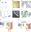
The N-Terminal Repeats of Mollusk VERL and Mammalian ZP2 Adopt a Common ZP-N Fold (A) Domain organization of red abalone VERL and mouse ZP2. Construct boundaries are marked by brackets and detailed in the Key Resources Table; regions corresponding to constructs whose structure was determined in this work are colored. Open circles and inverted tripods represent signal peptides and N-glycans, respectively. TM, transmembrane domain. Percentage sequence identity between VR1 or VR2 and VR3 is indicated below the respective domains; repeats 3–22 are ∼99% identical. (B) Crystal structures of red abalone VERL VR1+ and mouse ZP2 ZP-N1, shown in cartoon representation and rainbow-colored from blue (N terminus) to red (C terminus). ZP-N domain features are highlighted, with the two invariant disulfides with 1-4, 2-3 connectivity and the conserved Tyr residue in β strand F shown as dark magenta and orange sticks, respectively. The partially disordered fg loop of ZP2 is represented by a dashed line. A red ellipse marks β strand D, which belongs to different sheets in the two structures. N- and C-terminal residues defined in the electron density are indicated. (C) Structural comparison of VR1+ (salmon) and ZP-N1 (green) identifies a core of 52 residues that can be superimposed with a Cα RMSD of 1.9 Å. See also Figure S1 and Tables S1 and S2.
Figure S1
Figure S1
Structure Determination of mMBP-VR1+ and ZP2 ZP-N1, Related to Figure 1 (A) Coomassie-stained SDS-PAGE analysis of purified mMBP-VR1+. The relative shift in migration between samples run in non-reducing (NR) and reducing (R) conditions indicates presence of disulfide bonds. (B) Crystal of mMBP-VR1+. (C) SEC suggests that purified ZP2 ZP-N1 is a monomer. The elution volume (Ve) of standard markers is indicated. Right panel, SDS-PAGE analysis of the SEC peak. (D) Crystals of ZP2 ZP-N1. (E and F) 2mFo-DFc electron density maps contoured at 1 σ of mMBP-VR1+ (gray, mMBP; salmon, VR1+) and ZP2 ZP-N1 (green). (G and H) Topology diagrams of VR1+ and ZP2 ZP-N1. Secondary structure elements are colored as in Figure 1B and their boundaries and length are indicated; conserved ZP-N domain disulfides C1-C4 and C2-C3 are represented by magenta lines.
Figure 2
Figure 2
Identification of a Minimal, High-Affinity VERL/Lysin Complex (A–C) Coomassie-stained SDS-PAGE analysis of pull-down experiments of lysin co-transfected with different His-tagged VERL constructs. Lane 1 in (A) is a refolded lysin control. Open and closed circles in (C) indicate VR3 isoforms resulting from alternative signal peptide cleavages (see STAR Methods). (D) SEC analysis of purified VR1+ (top) and VR3 (middle) by themselves and mixed with lysinR in a 1:2 ratio. Peaks are normalized to 80 mAU. Bottom: SDS-PAGE analysis of SEC peak fractions. (E) MST analysis of lysinR interaction with VR1+, VR3, and negative control ZP2 ZP-N1. Results are shown as mean ± SD. See also Figure S2.
Figure S2
Figure S2
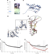
Structure Determination and Functional Analysis of LysinR, Related to Figure 2 (A) Coomassie-stained SDS-PAGE analysis of purified lysinR. (B) Orthorhombic (top panels) and monoclinic (bottom panel) crystals of lysinR. (C) The sulfur atoms of 6 Met residues are identified by a 5 σ anomalous difference map of lysinR (red mesh), which is shown superimposed onto the refined model of the protein. (D) Detail of the hypervariable N-terminal region of lysinR in the refined 0.99 Å resolution 2mFo-DFc electron density map of the protein, contoured at 1 σ. (E) Comparison of chains from different structures highlights the flexibility of lysin N terminus. Blue, orthorhombic lysinR; shades of green, chains of monoclinic lysinR; shades of gray, chains of PDB: 1LYN; yellow, PDB: 2LIS; shades of red, chains of PDB: 2LYN. (F and G) MST analysis of the interaction of lysinR with different VERL repeats. MST time traces obtained by titrating 10 nM labeled lysin with increasing concentrations of VR1+ up to 0.1 mM (F) and VR3 up to 2 μM (G). Traces corresponding to bound and unbound states are colored red and black, respectively, whereas traces corresponding to partially bound intermediates are shown in gray. VR3 binds to lysin with high affinity, but no binding is detected to VR1+.
Figure 3
Figure 3
Molecular Basis of VR3/Lysin Interaction (A) Cartoon representation of the VR3 (dark pink)/lysin (blue) complex, with N-glycans shown as sticks. The trigonal structure is shown here and subsequent figures. (B) Surface representations of VR3 (left) and lysin (right), highlighting hydrophobic regions (yellow) at the interface with the respective partners (cartoon). Main secondary structure elements involved in the interaction are marked. (C) Scheme of the interface. Interactions are represented by lines connecting residues and color coded by property as indicated below the panel. See also Figure S3, Figure S4, Figure S5, Figure S6 and Tables S4 and S5.
Figure S3
Figure S3
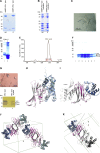
mMBP-Fused VR3 Binds Lysin and Crystallizes with Antiparallel Pairing of the E Strands of Two Molecules, Related to Figures 3 and 7 (A) Coomassie-stained SDS-PAGE analysis of His-pull-down experiments of individually expressed VR3, mMBP and mMBP-VR3 (lanes 1-3), as well as of the same constructs co-expressed with lysin (lanes 4-6). mMBP-VR3 and unfused VR3 bind lysin comparably. mMBP was used as negative control. (B) MST determination of mMBP-VR3/lysinR Kd shows that unfused and mMBP-fused VR3 bind to lysinR with similar affinity (compare with Figure 2E). Results are shown as mean ± SD. (C) Microcrystals of mMBP-VR3 on the mesh used for diffraction data collection. (D) VR3 (dark pink) and VR1 (salmon) can be superimposed over 81 residues with a Cα RMSD of 0.9 Å. Conserved ZP-N disulfide bonds are shown as yellow sticks; disordered loops are represented by dashed lines. (E) The asymmetric unit of the mMBP-VR3 crystal contains an antiparallel VR3 homodimer held together by interactions involving the β sheets E of opposite chains. The resulting interface is scored as highly significant by PISA (Krissinel and Henrick, 2007) and buries an average accessible surface area of 646 Å2. The overall arrangement of the two mMBP-VR3 chains is depicted in the left panel, and details of the 1 σ 2mFo-DFc electron density map of the interface region are shown in the right panel. Dashed lines indicate intermolecular hydrogen bonds.
Figure S4
Figure S4
Purification and Crystallization of Elastase-Treated (mMBP-)VR3/Lysin and Unfused VR3/Lysin, Related to Figures 3 and 4 (A) Coomassie-stained SDS-PAGE analysis of purified mMBP-VR3/lysin complex material. (B) Treatment of mMBP-VR3 lysin with elastase produces five major protein bands, indicated by red numbers. Based on immunoblot analysis (data not shown), digestion products are intact mMBP-VR3 (1), mMBP (2), partially degraded mMBP (3), lysin (4) and VR3 (5). (C) Crystals obtained using elastase-treated mMBP-VR3/lysin material. (D) Coomassie-stained SDS-PAGE of IMAC-purified VR3/lysin complex from HEK293S cells, before and after Endo H treatment. (E) SEC of the Endo H-treated VR3/lysin complex shows that it elutes as a single peak, which was collected into 7 fractions. (F) Coomassie-stained SDS-PAGE analysis of the fractions of the VR3/lysin complex SEC peak. Lane numbers match the peak fraction numbers in (E). Open and close circles indicate VR3 isoforms resulting from alternative signal peptide cleavages (see STAR Methods). (G) Trigonal crystals of the VR3/lysin complex (top) and silver-stained SDS-PAGE analysis of dissolved crystals (bottom). In lane 1, 2 μg of purified VR3/lysin were loaded; lane 2 shows material from 5 crystals of the complex. (H) The structure of mMBP-fused VR3 (gray) and orthorhombic lysinR (cyan) can be superimposed on the corresponding moieties of the VR3/lysin complex (dark pink and blue) with a Cα RMSD of 0.7 Å and 0.3 Å, respectively. This comparison indicates that no significant structural change occurs during complex formation. The mMBP moiety of mMBP-VR3 is not shown for simplicity. (I) Superimposition of the VR3 moieties of mMBP-VR3 (gray) and the VR3/lysin complex (dark pink) shows that mMBP (light gray) lies on the opposite side of VR3 as lysin (blue). This explains why mMBP fusion does not interfere with complex formation between VR3 and lysin. (J) The asymmetric unit of the triclinic crystal form contains two homodimers of VR3 (dark and light pink), each of which is bound to two molecules of lysin (blue and cyan). The unit cell is shown in green and crystal axes are indicated. (K) The asymmetric unit of the trigonal crystal form contains a single copy of the VR3/lysin complex (dark pink/blue), whose VR3 moiety is engaged in the same homodimer observed in the triclinic crystals by interacting with a symmetry-related VR3/lysin complex (light and dark gray). Unit cells and crystal axes are depicted as in (J).
Figure S5
Figure S5
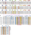
Sequence Comparison of VERL Repeats and Lysin from Different Haliotis Species, Related to Figures 3 and 6 (A) Multiple sequence alignment, showing the intra- and interspecies similarity of VR1, VR2 and VR3. Sequences are listed in order of decreasing similarity to red abalone VERL. Secondary structure, based on the crystal structures of red abalone VR1+, VR2+ (from chain B of the VR2+/lysin complex) and VR3 (from the trigonal VR3/lysin complex), is depicted on top; consensus sequences are shown at the bottom (cons., brown). Conserved ZP-N Cys are marked and their connectivity is indicated (magenta). Interface residues of the VR3/lysin and VR2+/lysin complexes are indicated by red boxes; corresponding positions in VR1 are outlined by dashed red boxes. Hydrophobic interface residues are highlighted in yellow. Positively selected residues (Galindo et al., 2003, Kresge et al., 2001) are marked by black circles above the alignment. Abalone species abbreviations are: RUF, H. rufescens (red); SOR, H. sorenseni (white); WAL, H. walallensis (flat); KAM, H. kamtschatkana (pinto); GIG, H. gigantea (giant); DIS, H. discus hannai (Japanese); COR, H. corrugata (pink); CRA, H. cracherodii (black); FUL, H. fulgens (green); DIV, H. diversicolor (variously colored); AUS, H. australis (Australian); VAR, H. varia (variable); OVI, H. ovina (sheep’s ear); ROE, H. roei (Roe’s); RUB, H. rubra (blacklip); CON, H. conicopora; SCA, H. scalaris (staircase); LAE, H. laevigata (greenlip); PUS, H. pustulata; MID, H. midae (perlemoen); CYC, H. cyclobates (whirling); IRI, H. iris (paua); TUB, H. tuberculata (green ormer). Californian species (Lee and Vacquier, 1995) are marked by an asterisk next to their name abbreviation. Consensus symbols: uppercase, high consensus (> 90%); lowercase, low consensus (> 50%); !, I or V; $, L or M; %, F or Y; #, N or D or Q or E. (B) Multiple sequence alignment of lysin. Conventions are as in (A), with interface residues of the VR3/lysin and VR2+/lysin complexes indicated by open red boxes in the alignment and closed red boxes below the consensus line, respectively. The secondary structure of red abalone lysin (from the trigonal VR3/lysin complex) is displayed, and solvent-exposed basic residues that do not interact with VR3 or VR2+ in the complex structures are highlighted in blue.
Figure S6
Figure S6
Glycans and Positively Selected Residues Do Not Influence VR3/Lysin Complex Formation, Related to Figure 3 (A and B) VR3 or VR3+ constructs carrying mutations of N-glycosylation sites (N373Q, N417Q, N438Q) or interdomain linker O-glycosylation sites (T456G, T459G, S460G, T467A, T470G, S471G, S472G, S478G, S479G, S485G, S489G) are significantly less glycosylated than counterpart wild-type proteins, but bind lysin equally well. (C) Surface representation of lysin bound to VR3 (depicted as dark pink cartoon), with positively selected residues highlighted in black. Only N82, L85 and K150 lie at the complex interface. (D) Close-up of the trigonal VR3/lysin complex, with the three positively selected residues of lysin at the interface with VR3 shown as sticks. Whereas N82 and L85 are conserved among all Californian species of abalone, K150 - which makes an ion pair with VR3 E384 - is variable. Note how the N-terminal region of lysin, which is only defined in the electron density map from F28 onward, is positioned away from interface with VR3. (E) Disruption of the lysin K150/VR3 E384 ion pair by individual or combined mutation of the interacting residues does not hinder complex formation. (F) A lysin mutant lacking hypervariable N-terminal residues R19-L29 is pulled down by VR3 as efficiently as wild-type lysin.
Figure 4
Figure 4
VR3/Lysin Complex Formation Depends on Both Hydrophobic and H-Bonding Interactions (A) Close up of the VR3/lysin interface, oriented as in the right panel of Figure 3B. Functionally important residues and surrounding hydrophobic amino acids are in stick representation. Only β strand E of VR3 is shown for clarity. Dashed black lines indicate hydrogen bonds. (B) Lysin α2 interface residues mutated in construct lysin_t (R74A, Y75A, T78A). (C–E) Functional analysis of VR3 and lysin interface mutants by His-pull-down. VR3_h, M389K; VR3_p, N388A; VR3_hp, N388A, M389K; lysin_h, F119S; lysin_d, T78A, H79A. Right panel of (E), anti-lysin immunoblot shows that individually expressed lysin_t is secreted as efficiently as wild-type lysin. See also Figures S4 and S5 and Tables S4 and S5.
Figure 5
Figure 5
Substitution of VR3 Interface Residues Explains Why VR1 Does Not Bind Lysin (A) VR1 surface colored by electrostatic potential. Circles mark non-positively selected amino acids of VR1 (salmon) that differ from VR3 residues (magenta) at the interface with lysin. (B) Unlike the corresponding region in VR1 (A), the interacting surface of VR3 (left) is electrostatically complementary to that of lysin (right). (C) A VR3 mutant where the residues highlighted in (A) are replaced by the corresponding residues of VR1 (VR3_mut, lane 2) does not pull down lysin. See also Figure S5 and Tables S1 and S4.
Figure 6
Figure 6
VR2/Lysin Recognition Contributes to the Species-Specificity of Gamete Interaction (A–B) His-pull-down analysis of lysins from different species of abalone co-expressed with (A) VR1+, VR1+2+, VR3+ or (B) VR2+ constructs of red abalone VERL. Like VR1+2+ (A, lane 4), VR2+ binds efficiently only to red abalone lysin (B, lane 1); however, different from VR1+2+, VR2+ is not well secreted by mammalian cells when it does not form a complex (B, lanes 2 and 3). (C) Polyclonal anti-lysin immunoblot analysis of the secretion levels of individually expressed lysins. (D) Cartoon representation of the crystal structure of the VR2+/lysin complex, with the two moieties of the VR2+ homodimer and lysin colored orange/yellow and blue, respectively. The intermolecular disulfide stabilizing the VR2+ homodimer is indicated by an arrow. (E) Details of non-covalent interactions mediating VR2+ homodimerization. (F) As observed in the case of VR3 (Figure 5B), the surface of VR2+ is electrostatically complementary to lysin. (G) MST analysis of red lysinR interaction with red VR1+2+ and VR1+, as well as negative control ZP2 ZP-N1. Results are shown as mean ± SD. (H) Amino acid substitutions converting the interface of red VR2 to that of pink do not change the species-specificity of the interaction between VR1+2+ and lysin. (I) Close-up of the VR2+/lysin complex structure, showing how the C-terminal region of red lysin interacts with the de loop of VR2+. (J) His-pull-down analysis of VR1+2+ co-transfected with N- and C-terminal variants of red and pink lysin. Bottom: An immunoblot with anti-lysin, showing the secretion levels of the same lysin constructs expressed individually. See also Figures S5 and S7, and Tables S4 and S6.
Figure S7
Figure S7
Crystal Structures of VR2+ and the VR2+/Lysin Complex, Related to Figures 6 and 7 (A) Crystal of free VR2+ grown in drops set up with the VR2+/lysin complex. (B) Silver-stained non-reducing SDS-PAGE analysis of a crystal like the one shown in (A) indicates that this exclusively contains a homodimeric, intermolecularly disulfide-bonded form of VR2+ (orange arrow). Due to Endo H treatment of N-glycans and a shorter linker with O-glycosylation site mutations, the VR2+ construct used for X-ray crystallography has a significantly smaller mass than the corresponding protein used for functional studies (Figures 2A and 6B). (C) Crystal structure of free VR2+ in cartoon representation (left panel), with the two moieties of the homodimer colored as in Figure 6D. The structure is essentially identical to that of lysin-bound VR2+ (right panel; RMSD 0.7 Å over 156 Cα atoms). As a consequence of the structural disorder of the C-terminal interdomain linker, the two intermolecular disulfide bonds involving C201 and C204 are not resolved in the electron density map of free VR2+ (left panel, thin ovals); similarly, only one of the disulfides is visible in the case of the VR2+/lysin complex (right panel, thick oval), where the linker packs against a symmetry-related copy of lysin (not shown). Disordered linkers and C201/C294 are represented by dotted lines and closed circles, colored according to the respective molecules. (D) Crystal of the VR2+/lysin complex.
Figure 7
Figure 7
The Repeated Structure of VERL Filaments Suggests a Mechanism for Egg Coat Recognition and Penetration by Sperm (A) Stacked VR2+ homodimers adopt a filament-like arrangement in the VR2+/lysin complex crystal. The boxed area suggests the repeat organization outlined in (B). (B) Possible architecture of VERL repeat branches. Filled rectangles represent individual repeats, colored as in the previous figures and connected by flexible interdomain linkers (thin gray lines). Brown staples represent VR2+ intermolecular disulfide bonds. Yellow ellipses and green tripods indicate hydrophobic lysin-binding sites and O-glycans, respectively. Stacking of homodimeric VERL repeats within each branch is based on the packing shown in (A) (black rectangle); lateral interaction between repeats of adjacent branches is supported by the VR3/VR3 contacts depicted in (C) (blue rectangle). (C) Surfaces mediating VR3/lysin interaction (center) make homomeric contacts in crystals of isolated lysin (left) and VR3 (right). (D) As exemplified by the VR3/lysin complex structure, VERL repeat-bound lysin exposes a highly basic surface to the solvent. (E) Proposed mechanism of VE recognition and non-enzymatic dissolution by lysin. Positively charged lysin molecules are represented by blue circles, with the hydrophobic VERL repeat-binding site shown as a yellow ellipse. (F) 100 ns molecular dynamics simulation of two facing lysin molecules bound to VR3 repeats representing adjacent branches of VERL. Strong electrostatic repulsion between the exposed basic surfaces of the lysin molecules causes the complexes to be pushed apart over time. Basic surface Lys and Arg residues are in sphere representation and colored red and orange, respectively. See also Figures S3 and S7, Tables S1, S3, and S4, and Movie S1.

Comment in

  • Sex at Atomic Resolution.
    Hwang JY, Chung JJ. Hwang JY, et al. Cell. 2017 Jun 15;169(7):1174-1176. doi: 10.1016/j.cell.2017.05.043. Cell. 2017. PMID: 28622504

Similar articles

Cited by

References

    1. Aagaard J.E., Vacquier V.D., MacCoss M.J., Swanson W.J. ZP domain proteins in the abalone egg coat include a paralog of VERL under positive selection that binds lysin and 18-kDa sperm proteins. Mol. Biol. Evol. 2010;27:193–203. - PMC - PubMed
    1. Abrahams J.P., Leslie A.G. Methods used in the structure determination of bovine mitochondrial F1 ATPase. Acta Crystallogr. D Biol. Crystallogr. 1996;52:30–42. - PubMed
    1. Adams P.D., Afonine P.V., Bunkóczi G., Chen V.B., Davis I.W., Echols N., Headd J.J., Hung L.W., Kapral G.J., Grosse-Kunstleve R.W. PHENIX: a comprehensive Python-based system for macromolecular structure solution. Acta Crystallogr. D Biol. Crystallogr. 2010;66:213–221. - PMC - PubMed
    1. Afonine P.V., Grosse-Kunstleve R.W., Echols N., Headd J.J., Moriarty N.W., Mustyakimov M., Terwilliger T.C., Urzhumtsev A., Zwart P.H., Adams P.D. Towards automated crystallographic structure refinement with phenix.refine. Acta Crystallogr. D Biol. Crystallogr. 2012;68:352–367. - PMC - PubMed
    1. Agirre J., Iglesias-Fernández J., Rovira C., Davies G.J., Wilson K.S., Cowtan K.D. Privateer: software for the conformational validation of carbohydrate structures. Nat. Struct. Mol. Biol. 2015;22:833–834. - PubMed

MeSH terms