. 2017 Jun 9;11(3):034117.
doi: 10.1063/1.4985158. eCollection 2017 May.

Amphiphilic nanoparticles suppress droplet break-up in a concentrated emulsion flowing through a narrow constriction

Affiliations

Amphiphilic nanoparticles suppress droplet break-up in a concentrated emulsion flowing through a narrow constriction

Ya Gai et al. Biomicrofluidics. .

Abstract

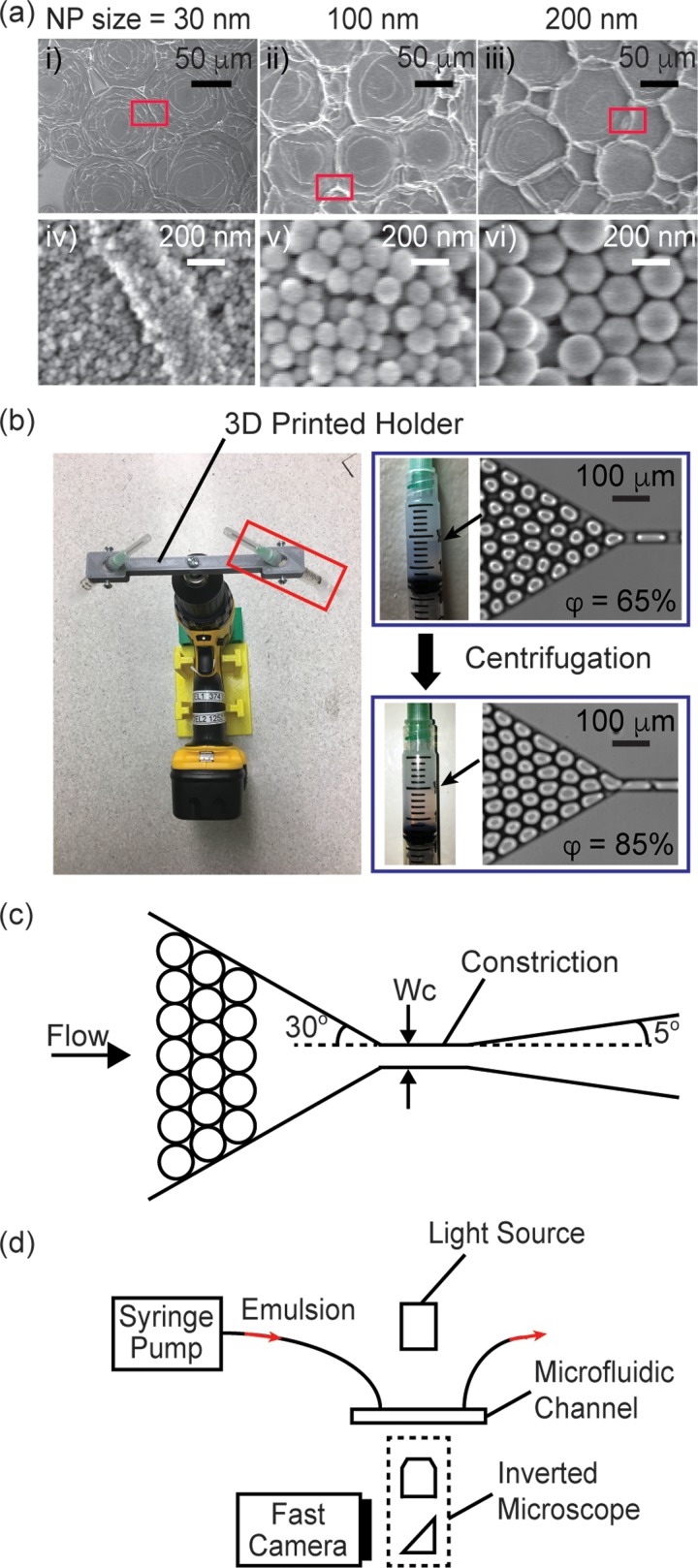
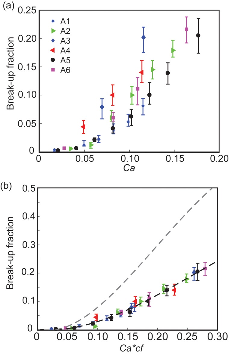
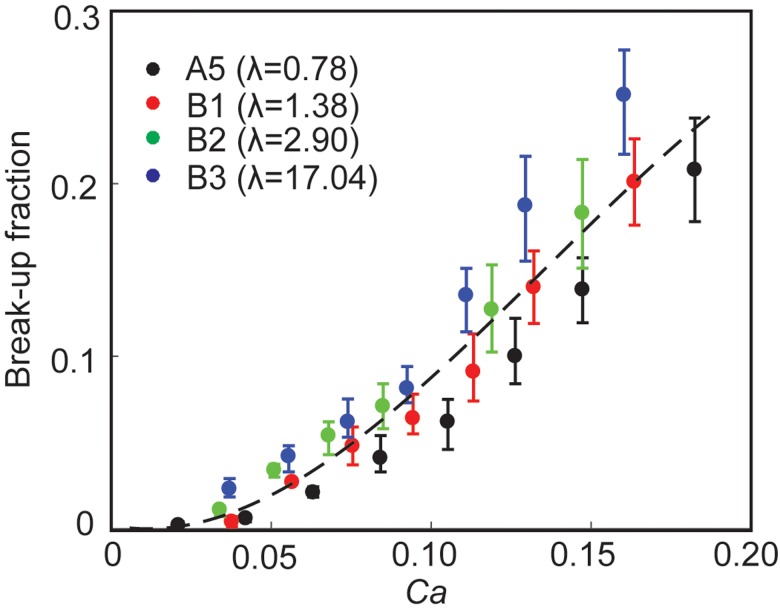
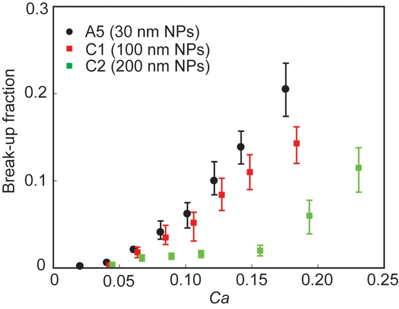
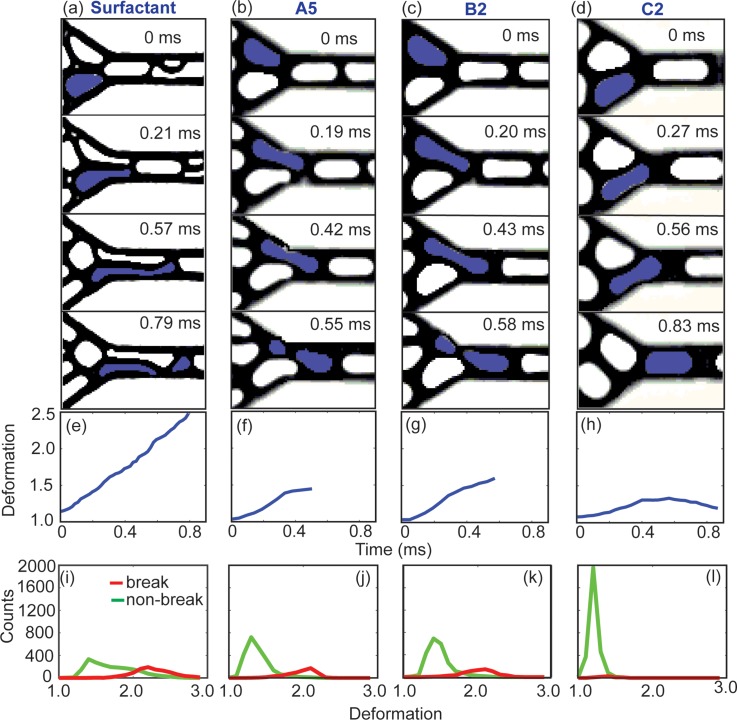
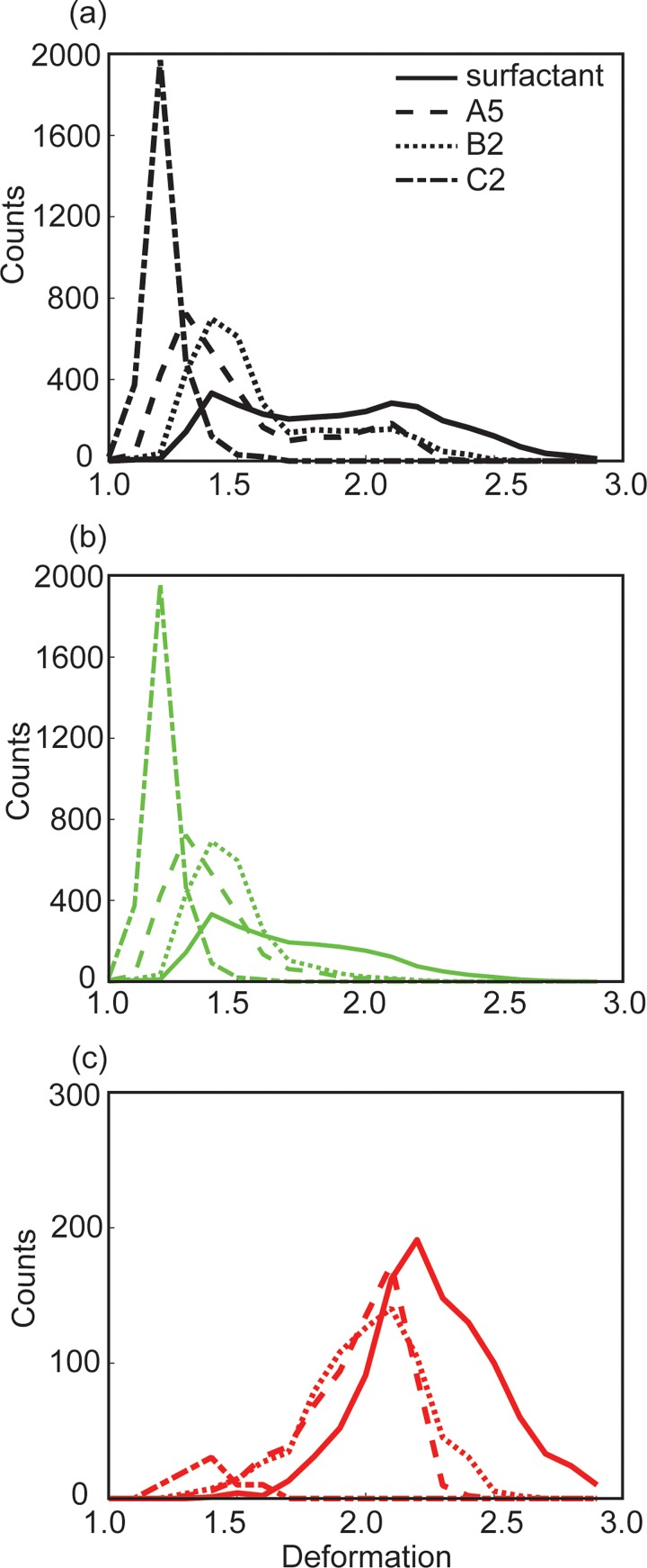
This paper describes the break-up behavior of a concentrated emulsion comprising drops stabilized by amphiphilic silica nanoparticles flowing in a tapered microchannel. Such geometry is often used in serial droplet interrogation and sorting processes in droplet microfluidics applications. When exposed to high viscous stresses, drops can undergo break-up and compromise their physical integrity. As these drops are used as micro-reactors, such compromise leads to a loss in the accuracy of droplet-based assays. Here, we show droplet break-up is suppressed by replacing the fluoro-surfactant similar to the one commonly used in current droplet microfluidics applications with amphiphilic nanoparticles as droplet stabilizer. We identify parameters that influence the break-up of these drops and demonstrate that break-up probability increases with increasing capillary number and confinement, decreasing nanoparticle size, and is insensitive to viscosity ratio within the range tested. Practically, our results reveal two key advantages of nanoparticles with direct applications to droplet microfluidics. First, replacing surfactants with nanoparticles suppresses break-up and increases the throughput of the serial interrogation process to 3 times higher than that in surfactant system under similar flow conditions. Second, the insensitivity of break-up to droplet viscosity makes it possible to process samples having different composition and viscosities without having to change the channel and droplet geometry in order to maintain the same degree of break-up and corresponding assay accuracy.


Figures

FIG. 1.
FIG. 1.
(a) SEM images of dried droplets that were stabilized by NPs with diameter of: (i), (iv) 30 nm, (ii), (v) 100 nm, and (iii), (vi) 200 nm, respectively. (iv)–(vi) are enlarged views corresponding to regions inside the red boxes in (i)–(iii), respectively. (b) (Left) Image of the electric drill/driver fitted with a custom 3D-printed syringe holder for centrifugation and concentration of the emulsion. (Right) The volume fraction of the emulsion increased from 65% to 85% after the centrifugation step. (c) Scheme of the channel. (d) Experimental setup.
FIG. 2.
FIG. 2.
Effect of confinement on the break-up of NP drops within a concentrated emulsion. (a) Break-up fraction as a function of capillary number (Ca) at different drop sizes and constriction geometries. The data are from experiments A1-A6 as listed in Table I. (b) Break-up fraction as a function of the product of capillary number (Ca) and confinement factor (cf). The black dashed line is a guide to the eye only. The gray dashed line is the visual guide adopted from surfactant drops from our previous work. See supplementary material, Fig. S1, of our prior work for a detail discussion of error bars.
FIG. 3.
FIG. 3.
Effect of viscosity ratio on break-up. Break-up fraction as a function of capillary number at different viscosity ratios (λ). The data are from experiments A5 (λ = 0.78), B1 (λ = 1.38), B2 (λ = 2.90), and B3 (λ = 17.04) as listed in Table I. The dashed line is for visual guide only.
FIG. 4.
FIG. 4.
Effect of particle size on break-up. Break-up fraction as a function of capillary number for drops stabilized by NPs with different sizes. The data are from experiments A5 (30 nm NPs), C1 (100 nm NPs), and C2 (200 nm NPs) as listed in Table I.
FIG. 5.
FIG. 5.
A series of snapshots showing the deformation of drops for: (a) surfactant drops, (b) NP drops in experiments A5, (c) B2, and (d) C2, respectively, all at capillary number Ca ∼ 0.15. The value of confinement factor cf is identical in (a)–(d). λ shown in (a) is identical to that in A5. (e)–(h) The deformation of the drop highlighted in blue as a function of time, corresponding to the snapshots in (a)–(d). (i)–(l) Histograms showing the distribution of the maximum deformation a drop experienced during its flow in the field of view as shown in (a)–(d). 3000 drops were recorded for each plot. The red curves denote drops that underwent break-up, and the green curves denote drops that did not undergo break-up.
FIG. 6.
FIG. 6.
(a) Distribution of the maximum deformation of 3000 drops, including both break-up and non-breakup drops. (b) The same distribution as that in (a), but for non-breakup drops only. (c) The same distribution as that in (a), but for break-up drops only. The curves in (a)–(c) correspond to datasets shown in Figs. 5(i)–5(l), respectively.

References

    1. Teh S.-Y., Lin R., Hung L.-H., and Lee A. P., Lab Chip 8(2), 198–220 (2008).10.1039/b715524g - DOI - PubMed
    1. Rosenfeld L., Lin T., Derda R., and Tang S. K., Microfluid. Nanofluid. 16(5), 921–939 (2014).10.1007/s10404-013-1310-x - DOI
    1. Breslauer D. N., Lee P. J., and Lee L. P., Mol. Biosyst. 2(2), 97–112 (2006).10.1039/b515632g - DOI - PubMed
    1. Köster S., Angile F. E., Duan H., Agresti J. J., Wintner A., Schmitz C., Rowat A. C., Merten C. A., Pisignano D., and Griffiths A. D., Lab Chip 8(7), 1110–1115 (2008).10.1039/b802941e - DOI - PubMed
    1. Kim M., Pan M., Gai Y., Pang S., Han C., Yang C., and Tang S. K., Lab Chip 15(6), 1417–1423 (2015).10.1039/C4LC01465K - DOI - PubMed