

Real time implementation of anti-scatter grid artifact elimination method for high resolution x-ray imaging CMOS detectors using Graphics Processing Units (GPUs)
- PMID: 28659654
- PMCID: PMC5484410
- DOI: 10.1117/12.2254120
Real time implementation of anti-scatter grid artifact elimination method for high resolution x-ray imaging CMOS detectors using Graphics Processing Units (GPUs)
Abstract
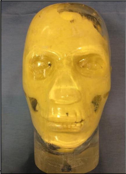
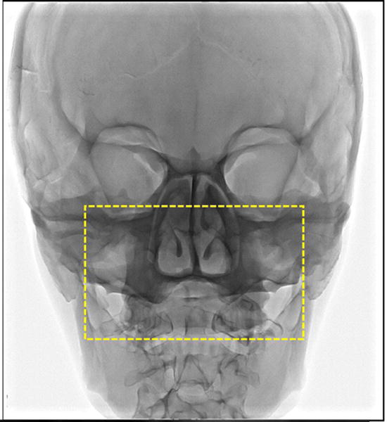
Scatter is one of the most important factors effecting image quality in radiography. One of the best scatter reduction methods in dynamic imaging is an anti-scatter grid. However, when used with high resolution imaging detectors these grids may leave grid-line artifacts with increasing severity as detector resolution improves. The presence of such artifacts can mask important details in the image and degrade image quality. We have previously demonstrated that, in order to remove these artifacts, one must first subtract the residual scatter that penetrates through the grid followed by dividing out a reference grid image; however, this correction must be done fast so that corrected images can be provided in real-time to clinicians. In this study, a standard stationary Smit-Rontgen x-ray grid (line density - 70 lines/cm, grid ratio - 13:1) was used with a high-resolution CMOS detector, the Dexela 1207 (pixel size - 75 micron) to image anthropomorphic head phantoms. For a 15 × 15 cm field-of-view (FOV), scatter profiles of the anthropomorphic head phantoms were estimated then iteratively modified to minimize the structured noise due to the varying grid-line artifacts across the FOV. Images of the head phantoms taken with the grid, before and after the corrections, were compared, demonstrating almost total elimination of the artifact over the full FOV. This correction is done fast using Graphics Processing Units (GPUs), with 7-8 iterations and total time taken to obtain the corrected image of only 87 ms, hence, demonstrating the virtually real-time implementation of the grid-artifact correction technique.
Keywords: CMOS detector; GPUs; anthropomorphic head phantoms; anti-scatter grid; grid artifacts; high resolution detector; iterative method; real time correction; scatter estimation; x-ray imaging.
Figures


Similar articles
-
Anti-scatter grid artifact elimination for high-resolution x-ray imaging detectors without a prior scatter distribution profile.Proc SPIE Int Soc Opt Eng. 2018 Feb;10573:1057367. doi: 10.1117/12.2293660. Epub 2018 Mar 9. Proc SPIE Int Soc Opt Eng. 2018. PMID: 29899590 Free PMC article.
-
Scatter estimation and removal of anti-scatter grid-line artifacts from anthropomorphic head phantom images taken with a high resolution image detector.Proc SPIE Int Soc Opt Eng. 2016 Feb 27;9783:978364. doi: 10.1117/12.2216833. Epub 2016 Mar 31. Proc SPIE Int Soc Opt Eng. 2016. PMID: 28649162 Free PMC article.
-
Anti-scatter grid artifact elimination for high resolution x-ray imaging CMOS detectors.Proc SPIE Int Soc Opt Eng. 2015;9412:941243. doi: 10.1117/12.2081430. Epub 2015 Mar 18. Proc SPIE Int Soc Opt Eng. 2015. PMID: 26877578 Free PMC article.
-
Limitations of anti-scatter grids when used with high resolution image detectors.Proc SPIE Int Soc Opt Eng. 2014 Mar 19;9033:903362. doi: 10.1117/12.2043063. Proc SPIE Int Soc Opt Eng. 2014. PMID: 25309101 Free PMC article.
-
The principles and effectiveness of X-ray scatter correction software for diagnostic X-ray imaging: A scoping review.Eur J Radiol. 2023 Jan;158:110600. doi: 10.1016/j.ejrad.2022.110600. Epub 2022 Nov 17. Eur J Radiol. 2023. PMID: 36444818
Cited by
-
A new software scheme for scatter correction based on a simple radiographic scattering model.Med Biol Eng Comput. 2019 Feb;57(2):489-503. doi: 10.1007/s11517-018-1893-1. Epub 2018 Sep 19. Med Biol Eng Comput. 2019. PMID: 30232700
-
Anti-scatter grid artifact elimination for high-resolution x-ray imaging detectors without a prior scatter distribution profile.Proc SPIE Int Soc Opt Eng. 2018 Feb;10573:1057367. doi: 10.1117/12.2293660. Epub 2018 Mar 9. Proc SPIE Int Soc Opt Eng. 2018. PMID: 29899590 Free PMC article.
References
-
- Neitzel U. Grids or air gaps for scatter reduction in digital radiography: a model calculation. Medical physics. 1992;19(2):475–481. http://www.ncbi.nlm.nih.gov/pubmed/1584148. - PubMed
-
- Barnes GT. Contrast and scatter in x-ray imaging. Radiographics : a review publication of the Radiological Society of North America Inc. 1991;11(2):307–323. http://www.ncbi.nlm.nih.gov/pubmed/2028065. - PubMed
-
- Bednarek DR, Rudin S, Wong R. Artifacts produced by moving grids. Radiology. 1983;147(1):255–258. http://www.ncbi.nlm.nih.gov/pubmed/6828740. - PubMed
-
- Rudin S, Bednarek DR, Hoffman KR. Endovascular image-guided interventions (EIGIs) Med Phys. 2008;35(1):301–309. http://www.pubmedcentral.gov/articlerender.fcgi?artid=2669303. - PMC - PubMed
-
- Gauntt DM, Barnes GT. Grid line artifact formation: A comprehensive theory. Medical physics. 2006;33(6):1668–1677. http://www.ncbi.nlm.nih.gov/pubmed/16872074. - PubMed
Grants and funding
LinkOut - more resources
Full Text Sources
Other Literature Sources