. 2017 Jul 19;95(2):412-423.e4.
doi: 10.1016/j.neuron.2017.06.019. Epub 2017 Jul 6.

Network-Level Control of Frequency Tuning in Auditory Cortex

Affiliations

Network-Level Control of Frequency Tuning in Auditory Cortex

Hiroyuki K Kato et al. Neuron. .

Abstract

Lateral inhibition is a fundamental circuit operation that sharpens the tuning properties of cortical neurons. This operation is classically attributed to an increase in GABAergic synaptic input triggered by non-preferred stimuli. Here we use in vivo whole-cell recording and two-photon Ca2+ imaging in awake mice to show that lateral inhibition shapes frequency tuning in primary auditory cortex via an unconventional mechanism: non-preferred tones suppress both excitatory and inhibitory synaptic inputs onto layer 2/3 cells ("network suppression"). Moreover, optogenetic inactivation of inhibitory interneurons elicits a paradoxical increase in inhibitory synaptic input. These results indicate that GABAergic interneurons regulate cortical activity indirectly via the suppression of recurrent excitation. Furthermore, the network suppression underlying lateral inhibition was blocked by inactivation of somatostatin-expressing interneurons (SOM cells), but not parvalbumin-expressing interneurons (PV cells). Together, these findings reveal that SOM cells govern lateral inhibition and control cortical frequency tuning through the regulation of reverberating recurrent circuits.


Figures

Figure 1
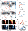
Figure 1. Lateral Inhibition in Auditory Cortex of Awake Mice
(A) Top, imaging schematic. Bottom, in vivo image of GCaMP6s (green)- and tdTomato (red)-expressing cells in L2/3 of A1. (B) Frequency tuning of two representative L2/3 pyramidal cells measured with two-photon calcium imaging. Traces are average responses (five trials) for each frequency-intensity pair. Red and blue lines outline excitatory and suppressive TRFs, respectively. (C) Lateral inhibition is prominent at high frequencies. Summary plot of excitatory and suppressive TRFs averaged across all cells with excitatory responses (n = 749 cells, 8 mice). Responses are centered at the best frequency (BF) for excitation and normalized to the maximum response of each neuron. (D) Cellular level tonotopic organization of A1. Top left, intrinsic signal imaging of responses to pure tones (3, 10, and 30 kHz) superimposed on image of cortical vasculature. A1, primary auditory cortex; A2, secondary auditory cortex; AAF, anterior auditory field. Black squares, locations of two-photon imaging. Top right, map of imaged pyramidal cells. Bottom, activity maps showing the characteristic frequency for excitation (CFexc) and suppression (CFsup) of the imaged cells. (E) Mismatch in the frequency tuning of excitation and suppression along the A1 tonotopic axis. Top, image of intrinsic signal showing reference points used for normalizing distance along the A1 tonotopic axis across animals. Middle, CFexc of individual cells coheres to the macroscopic tonotopy of A1. Bottom, mapping CFsup shows that tone-evoked suppression is less sharply aligned to A1 tonotopy and high frequencies are uniformly overrepresented.
Figure 2
Figure 2. Membrane Hyperpolarization and Unconventional Increase in Cell Input Resistance Underlie Lateral Inhibition
(A) Top, recording schematic and membrane potential responses of a representative cell to tones (nine frequencies, 70 dB, 200 ms) show shift from depolarization to hyperpolarization as frequency increases. Spikes digitally removed. Bottom left, representative cell with regular spiking response in current-clamp (400 pA current step). Bottom right, summary data for spike half-maximum width. The distribution shows a single cluster with values typical for pyramidal cells (1.22 ± 0.07 ms, n = 8 cells). Rec, recording pipette. Red line, mean. (B) Top, hyperpolarization and spike suppression in response to non-preferred tone (30 kHz) in a representative cell. Gray traces, five consecutive trials near firing threshold. Black trace, mean membrane potential across trials after removing spikes. Bottom left, summary data of peak hyperpolarization evoked by non-preferred tones (−8.8 ± 0.9 mV, n = 10 cells, p = 4×10⁻⁶). Bottom right, summary data showing the suppression of spikes during non-preferred tones (95% ± 3% suppression, n = 6 cells, **p = 2 × 10⁻³). (C) Cell input resistance increases during inhibition at non-preferred frequencies. Top, membrane response to current steps (I, −100 pA) in a representative cell before (Baseline) and during a non-preferred tone (bar, 30 kHz). Traces are averages of interleaved trials in which the current step was before (black) or during (blue) the tone. Bottom left, membrane response to current injection during the tone overlaid on the baseline response indicates an increase in membrane resistance. The membrane response to current steps during the tone (blue trace) was obtained by subtracting tone-evoked responses without current steps. Bottom right, summary of cell input resistance (Rin) change during non-preferred tones (n = 6 cells, 4 mice). Red bars, mean. *p = 0.0297. Results are mean ± SEM.
Figure 3
Figure 3. Non-preferred Stimuli Suppress Spontaneous Synaptic Excitation and Inhibition during Lateral Inhibition
(A) Top, recording schematic. Bottom left, voltage-clamp recordings show continuous, high-frequency barrages of spontaneous IPSCs (top) and EPSCs (bottom). Dashed lines indicate putative “baseline” current levels when spontaneous activity is low. Bottom right, traces from the same cell on a faster timescale show that a non-preferred tone suppresses both spontaneous EPSCs and IPSCs. Five consecutive trials are displayed in different colors. Black bars, tone. (B) Summary of the reduction of spontaneous synaptic activity determined from membrane current standard deviation (std) before and during non-preferred tones. Standard deviations of IPSCs (top) and EPSCs (bottom) are reduced during tones (IPSC, 36% ± 6%, n = 16 cells, ***p = 8 × 10⁻⁴; EPSC, 26% ± 4%, n = 23 cells, ***p = 6 × 10⁻⁵). Results are mean ± SEM.
Figure 4
Figure 4. Preferred Frequencies Evoke Fast, Onset-Locked EPSCs and IPSCs, while Non-preferred Frequencies Elicit Slow Network Suppression of Spontaneous Synaptic Activity
(A) Frequency tuning of tone-evoked EPSCs and IPSCs in one cell. Traces are average responses for each frequency-intensity pair. Red lines outline TRF region with fast, onset-locked components (EPSCON and IPSCON), blue lines indicate region with slow network suppression (EPSCNS and IPSCNS). (B) EPSC and IPSC from (A) averaged across frequencies with onset-locked responses (A and C, red) and network suppression (B and D, blue). Gray dotted lines mark windows for measuring individual components. (C) TRFs for EPSCON, IPSCON, EPSCNS, and IPSCNS averaged across cells (n = 23 cells, 17 mice). Responses are centered at EPSCON best frequency (BF) for each cell. (D) Summary of the frequency tuning of the four components at 50–70 dB. Response amplitudes are normalized to their individual peaks. Dark line, mean; shading, SEM.
Figure 5
Figure 5. Suppression of Interneurons Causes a Paradoxical Increase in Pyramidal Cell-Inhibitory Synaptic Current
(A) Left, schematic of optogenetic inactivation of SOM cells during in vivo voltage-clamp recording. Circuit based on Pfeffer et al., 2013. Middle, photoinactivation of SOM cells increases spontaneous EPSCs and IPSCs. Traces show average responses across experiments (n = 12 cells, 8 mice). Dark trace, mean across cells. Shading, SEM. Orange bars, LED. Right, blow-up of the traces at LED onset shows the transient reduction in inhibition (red arrowhead) that precedes the paradoxical increase in IPSC. (B) PV cell inactivation experiments. EPSCs and IPSCs as shown in A (n = 9 cells, 5 mice).
Figure 6
Figure 6. SOM Cells Trigger Network Suppression Underlying Lateral Inhibition
(A) SOM cell inactivation reduces tone-evoked network suppression. Top, schematic. Bottom, tone-evoked EPSCs and IPSCs of a representative cell with (brown) and without (black) SOM cell photoinactivation. Responses during photoinactivation were evoked 300 ms after LED onset and baselined to the 50 ms period before tone onset. Preferred and non-preferred tones (black bars, 70 dB) are 8.4 and 36.7 kHz, respectively. (B) Average magnitude of synaptic currents (EPSCON, IPSCON, EPSCNS, and IPSCNS) during LED on and LED off trials for responsive cell-tone pairs (n = 7 cells, 5 mice) plotted on log-modulus scale. Dashed lines, unity. Black crosses, average. (C) PV cell inactivation enhances network suppression. Top, schematic. Bottom, tone-evoked EPSCs and IPSCs of a representative cell with (brown) and without (black) PV cell photoinactivation. Preferred and non-preferred tones (black bars, 70 dB) are 13.7 and 36.7 kHz, respectively. (D) Average magnitude of response components during LED on and LED off trials for responsive cell-tone pairs (n = 8 cells, 5 mice).
Figure 7
Figure 7. SOM Cells Receive Broadly Tuned Excitation
(A) Top, approach. Bottom, frequency tuning of representative SOM cell. Red, outline of excitatory TRF. (B) Top, map of characteristic frequency for excitation (n = 142 cells, 5 mice) shows that SOM cells are tuned and aligned to the A1 tonotopic axis. Bottom, map of CF for suppression. Red lines, single exponential fit to data. (C) TRF for SOM cells reveal broadly tuned excitation and no lateral inhibition. Data are centered at the best frequency for excitation and normalized to the maximum response of each neuron. (D) Top, approach. Bottom, frequency tuning of representative PV cell with excitatory (red) and suppressive (blue) TRF. (E) Maps of characteristic frequencies for excitation and suppression of PV cells (n = 101 cells, 6 mice) are similar to pyramidal cells. (F) TRFs for PV cells reveal excitation and lateral inhibition similar to pyramidal cells.
Figure 8
Figure 8. SOM Cells Inhibit Wide Regions of Cortical Space
(A) Left, schematic of brain slice experiment using focal illumination along the A1 tonotopic axis to test input to L2/3 pyramidal cells from ChR2-expressing SOM and PV cells. Middle, IPSCs evoked by light ramps (blue) at increasing horizontal distances from the recorded cell body (0 μm) in a slice expressing ChR2 in SOM cells (upper traces) or PV cells (bottom traces). Right, summary showing that SOM cells (red, n = 12 cells, 5 mice) provide inhibition over a greater horizontal distance than PV cells (black, n = 12 cells, 6 mice). Data (mean ± SEM) are fit with a single exponential. Normalized IPSC at 300 μm: PV = 0.03 ± 0.01, SOM= 0.26 ± 0.05, p = < 0.001. (B) Same as in A but focal illumination is applied along a cortical column. Distance is plotted from cell body in L2/3 (0 μm) toward the white matter. Normalized IPSC at 300 μm: PV = 0.04 ± 0.03, SOM = 0.47 ± 0.07, p = < 0.001.

References

    1. Adesnik H, Scanziani M. Lateral competition for cortical space by layer-specific horizontal circuits. Nature. 2010;464:1155–1160. - PMC - PubMed
    1. Adesnik H, Bruns W, Taniguchi H, Huang ZJ, Scanziani M. A neural circuit for spatial summation in visual cortex. Nature. 2012;490:226–231. - PMC - PubMed
    1. Atallah BV, Bruns W, Carandini M, Scanziani M. Parvalbumin-expressing interneurons linearly transform cortical responses to visual stimuli. Neuron. 2012;73:159–170. - PMC - PubMed
    1. Calford MB, Semple MN. Monaural inhibition in cat auditory cortex. J Neurophysiol. 1995;73:1876–1891. - PubMed
    1. Carandini M, Ferster D. Membrane potential and firing rate in cat primary visual cortex. J Neurosci. 2000;20:470–484. - PMC - PubMed