

doi: 10.1039/c4sc03495c.
Epub 2015 Jan 7.
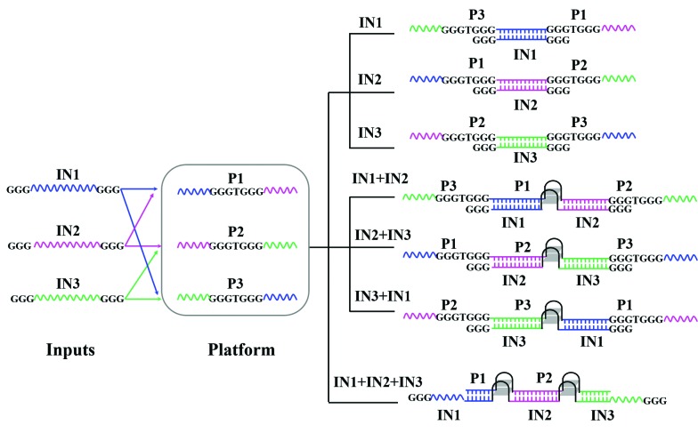
DNA-based visual majority logic gate with one-vote veto function
Affiliations
- PMID: 28706647
- PMCID: PMC5495993
- DOI: 10.1039/c4sc03495c
Item in Clipboard
DNA-based visual majority logic gate with one-vote veto function
Chem Sci.
.
Abstract
A molecular logic gate is a basic element and plays a key role in molecular computing. Herein, we have developed a label-free and enzyme-free three-input visual majority logic gate which is realized for the first time according to DNA hybridization only, without DNA replacement and enzyme catalysis. Furthermore, a one-vote veto function was integrated into the DNA-based majority logic gate, in which one input has priority over other inputs. The developed system can also implement multiple basic and cascade logic gates.
Figures
References
-
- de Silva P. A., Gunaratne N. H. Q., McCoy C. P. Nature. 1993;364:42–44.
-
- Adleman L. Science. 1994;266:1021–1024. - PubMed
-
- Xie Z., Wroblewska L., Prochazka L., Weiss R., Benenson Y. Science. 2011;333:1307–1311. - PubMed
-
- Magri D. C., Brown G. J., McClean G. D., de Silva A. P. J. Am. Chem. Soc. 2006;128:4950–4951. - PubMed
-
- Genot A. J., Bath J., Turberfield A. J. J. Am. Chem. Soc. 2011;133:20080–20083. - PubMed
LinkOut - more resources
Full Text Sources
Other Literature Sources