Review
. 2017 Mar 27;4(7):1700029.
doi: 10.1002/advs.201700029. eCollection 2017 Jul.

Recent Progress on Piezoelectric and Triboelectric Energy Harvesters in Biomedical Systems

Affiliations
Review

Recent Progress on Piezoelectric and Triboelectric Energy Harvesters in Biomedical Systems

Qiang Zheng et al. Adv Sci (Weinh). .

Abstract

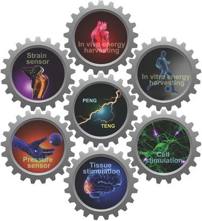
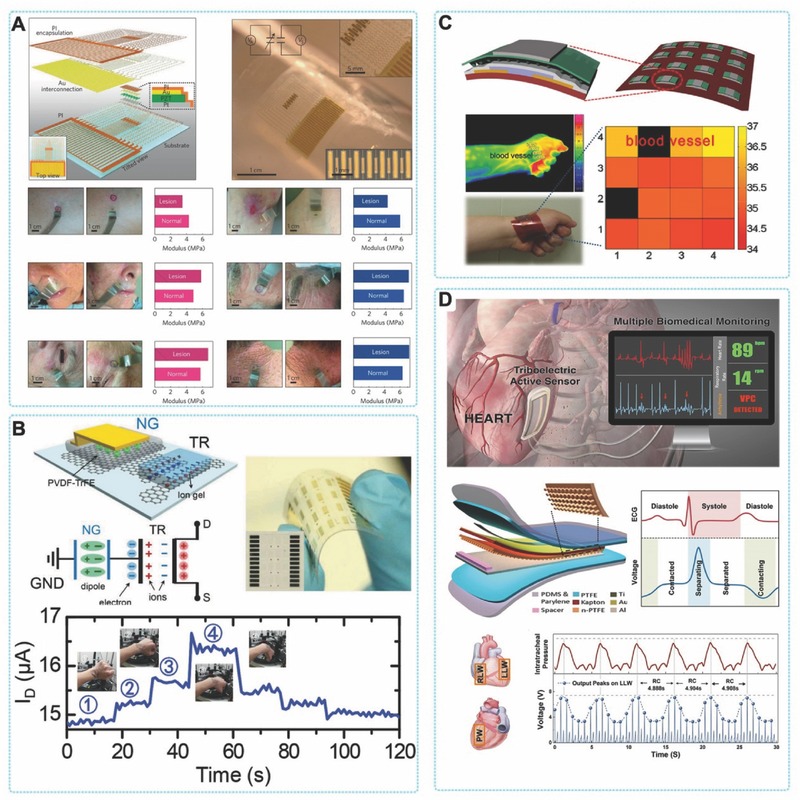
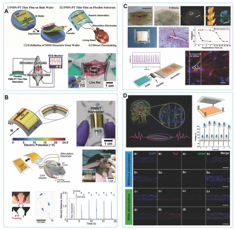
Implantable medical devices (IMDs) have become indispensable medical tools for improving the quality of life and prolonging the patient's lifespan. The minimization and extension of lifetime are main challenges for the development of IMDs. Current innovative research on this topic is focused on internal charging using the energy generated by the physiological environment or natural body activity. To harvest biomechanical energy efficiently, piezoelectric and triboelectric energy harvesters with sophisticated structural and material design have been developed. Energy from body movement, muscle contraction/relaxation, cardiac/lung motions, and blood circulation is captured and used for powering medical devices. Other recent progress in this field includes using PENGs and TENGs for our cognition of the biological processes by biological pressure/strain sensing, or direct intervention of them for some special self-powered treatments. Future opportunities lie in the fabrication of intelligent, flexible, stretchable, and/or fully biodegradable self-powered medical systems for monitoring biological signals and treatment of various diseases in vitro and in vivo.

Keywords: biomedicine; piezoelectric nanogenerators; self‐powered systems; triboelectric nanogenerators.


Figures

Figure 1
Figure 1
Recent applications of PENGs and TENGs in biomedical field.
Figure 2
Figure 2
Mechanism of piezoelectricity. A) Atomic model of the wurtzite‐structured ZnO. B) Different piezopotential in tension and compression modes of the PENG. C) Numerical calculation of the piezoelectric potential distribution in a ZnO nanowire under axial strain. Reproduced with permission.[[qv: 20a]] Copyright 2009, AIP Publishing LLC. D) Band diagram for the charge outputting and flowing processes in the PENG. Reproduced with permission.[[qv: 20b]]
Figure 3
Figure 3
The four fundamental modes of TENGs: A) vertical contact‐separation mode; B) Lateral‐sliding mode; C) freestanding triboelectric‐layer mode, and D) single‐electrode mode.
Figure 4
Figure 4
PENGs based on lateral ZnO nanowires. A,B) single nanowire based PENG fixed on flexible substrate. Reproduced with permission.27 Copyright 2009, Nature Publishing Group and American Chemical Society. C) Structure and optical images of a flexible lateral‐nanowire‐array integrated PENG. Reproduced with permission.28 Copyright 2010, Nature Publishing Group. D) Fabrication process of a flexible PENG based upon a lateral ZnO NW array. Reproduced with permission.12 Copyright 2010, American Chemical Society.
Figure 5
Figure 5
PENGs based on lateral ZnO nanowires. A) Experimental setup, internal structure, and mechanism of PENG fabricated by ZnO NWs vertically grown radially around textile fibers. Reproduced with permission.36 Copyright 2008, Nature Publishing Group. B) PENG prepared by growing ZnO NW arrays on graphene substrate. Reproduced with permission.34 C) PENG based on vertical ZnO nanowire arrays that grown by low‐temperature hydrothermal decomposition, which covered in PMMA by spin coating. Reproduced with permission.28 Copyright 2010, Nature Publishing Group. D) Super‐flexible ZnO based PENG with Al foil as both the substrate and the electrode. Reproduced with permission.35
Figure 6
Figure 6
PENGs with thin film structure. A) A schematic illustration of the fabrication process of the flexible and large‐area PZT thin‐film PENG using the ILLO process. Reproduced with permission.14 B) Thin‐film PENG based on laterally‐aligned PZT nanofibers. Reproduced with permission.41 Copyright 2010, American Chemical Society. C) Flexible BaTiO3 thin film PENG. Reproduced with permission.[[qv: 44b]] Copyright 2010, American Chemical Society. D) Thin film (P(VDF‐TrFE)) based PENG on flexible substrates. Reproduced with permission.51 Copyright 2011, Elsevier. E) Porous PENG based on PVDF film. Reproduced with permission.[[qv: 49b]]
Figure 7
Figure 7
Device structure design and material selection of flexible TENGs. A) The typical arch shaped TENG. Reproduced with permission.[[qv: 22b]] Copyright 2012, American Chemical Society. B) Stacked arch‐shaped TENGs. Reproduced with permission.67 Copyright 2013, Elsevier. C) Zigzag TENGs. Reproduced with permission.68 Copyright 2013, American Chemical Society. D, E) Stretchable TENGs. Reproduced with permissions.72, 73 Copyright 2016, the American Association for the Advancement of Science and the American Chemical Society. F) Fiber shaped TENG. Reproduced with permission.[[qv: 73b]] Copyright 2016, The Nature Publishing Group. G) Transparent polymer based TENG. Reproduced with permission.63 Copyright 2012, the American Chemical Society. H) Graphene based TENG. Reproduced with permission.[[qv: 56a]] I) CNT based TENG. Reproduced with permission.58 J) Bio‐degradable TENG.
Figure 8
Figure 8
In vivo energy harvesting by PENGs and TENGs. A) The first demonstration of in vivo biomechanical‐energy harvesting using a single nanowire based PENG. Reproduced with permission.76 B) Conformal energy harvesting from heart/lung by PZT based PENG. Reproduced with permission.31 Copyright 2014, National Academy of Sciences. C) Flexible PVDF based PENG for harvesting energy from ascending aorta. Reproduced with permission.78 Copyright 2015, Elsevier. D) The first demonstration of implantable TENG for harvesting biomechanical energy.[[qv: 68b]] E) Wireless cardiac monitoring system powered by iTENG.82
Figure 9
Figure 9
Active pressure/strain sensor based on PENG and TENG. A) Conformal modulus sensor based on PZT. Reproduced with permission.90 Copyright 2015, Nature Publishing Group. B) Active‐matrix strain sensor based on a PENG‐powered graphene transistor. Reproduced with permission.96 C) Structure of an OFET composed of microstructured P(VDF‐TrFE). Reproduced with permission.[[qv: 83a]] D) Implantable active sensor based on TENG. Reproduced with permission.92 Copyright 2016, American Chemistry Society.
Figure 10
Figure 10
Direct stimulation on cell, tissue and organ by PENG and TENG. A) A schematic of the experimental setup for artificial cardiac pacemaking using the electric output from the flexible PMN‐PT thin‐film PENG. Reproduced with permission.15 B) Self‐powered deep brain stimulator using the electric output from thin‐film PENG. Reproduced with permission.103 Copyright 2015, Royal Society of Chemistry. C) Electrical stimulation for neuron orientation based on BD‐TENG. D) A self‐powered neural differentiation system with a step‐driven TENG as the electrical simulation power source. Reproduced with permission.106 Copyright 2016, American Chemistry Society.

References

    1. a) Nelson G. D., Tex. Heart. Inst. J. 1993, 20, 12; - PMC - PubMed
    2. b) Cheng A., Tereshchenko L. G., J Electrocardiol. 2011, 44, 611; - PubMed
    3. c) Bolz A., in Springer Handbook of Medical Technology, (Ed: Kramme R., Hoffmann K.‐P.), Springer, Heidelberg, Germany: 2012, 767;
    4. d) Bonawitz S. C., Ann Plas Surg 2012, 69, 292; - PubMed
    5. e) Majerus S. J. A., Garverick S. L., Suster M. A., Fletter P. C., Damaser M. S., ACM J. Emerg. Tech. Com. 2012, 8, 11; - PMC - PubMed
    6. f) Rotariu C., Manta V., Costin H., Proceedings of the 2012 International Conference and Exposition on Electrical and Power Engineering (Epe 2012) 2012, 845;
    7. g) Garrigue S., Boveda S., Ritter P., in Dawn and Evolution of Cardiac Procedures, (Ed: Picichè M.), Springer, Milan, Italy: 2013, 253.
    1. a) Hannig J., Siekmeier R., Wien Klin. Wochenschr. 2016, 128, S262;
    2. b) Mond H. G., Sloman J. G., Edwards R. H., Pace 1982, 5, 278. - PubMed
    1. a) Akbari S., Shea H. R., Sens. Actuators A 2012, 186, 236;
    2. b) Knabe C., Ducheyne P., in Comprehensive Biomaterials, 1st Ed., (Ed: Ducheyne P.), Elsevier, Oxford, UK: 2011, p. 257;
    3. c) Soon C. F., Youseffi M., Berends R. F., Blagden N., Denyer M. C. T., Biosens. Bioelectron. 2013, 39, 14. - PubMed
    1. a) Ko W. H., ACM J. Emerg. Tech. Com. 2012, 8, 8; - PMC - PubMed
    2. b) von Lueder T. G., Krum H., Heart 2012, 98, 967; - PubMed
    3. c) Kennergren C., Europace 2013, 15, 165. - PubMed
    1. a) Mallela V. S., Ilankumaran V., Rao N. S., Indian Pacing and Electrophysiology Journal 2004, 4, 201; - PMC - PubMed
    2. b) Horlbeck F. W., Mellert F., Kreuz J., Nickenig G., Schwab J. O., J Cardiovasc. Electrophysiol. 2012, 23, 1336. - PubMed