Comparative Study
. 2017 Jul 24;12(7):e0178602.
doi: 10.1371/journal.pone.0178602. eCollection 2017.

Similarities and differences between on-scalp and conventional in-helmet magnetoencephalography recordings

Affiliations
Comparative Study

Similarities and differences between on-scalp and conventional in-helmet magnetoencephalography recordings

Lau M Andersen et al. PLoS One. .

Abstract

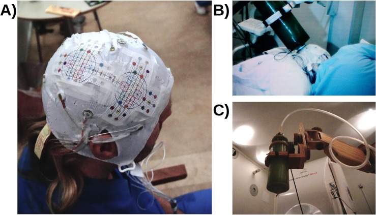
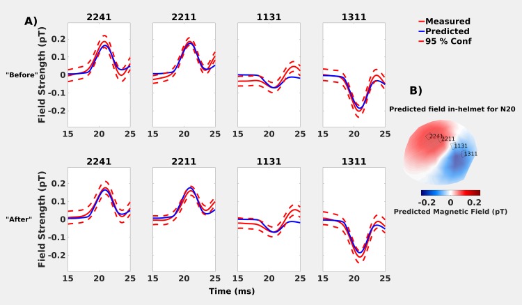
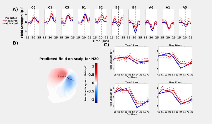
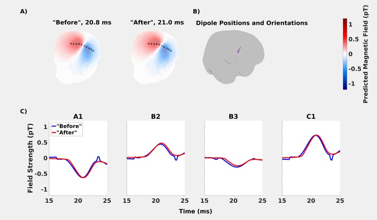
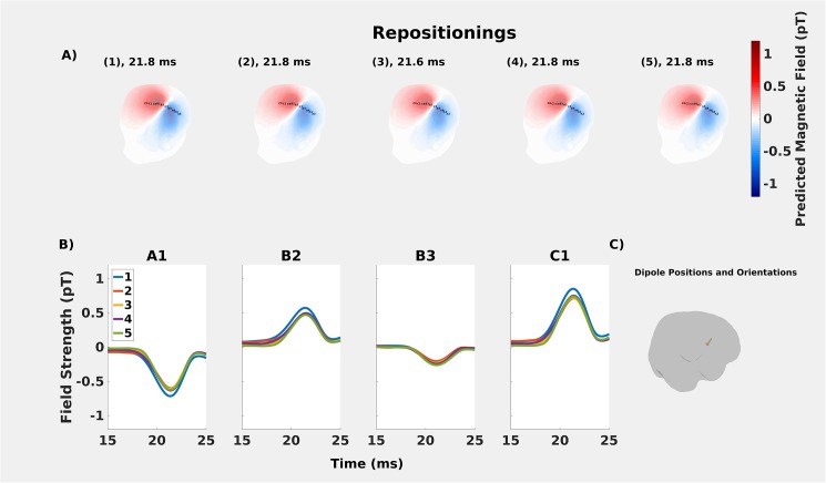
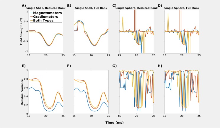
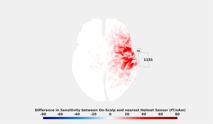
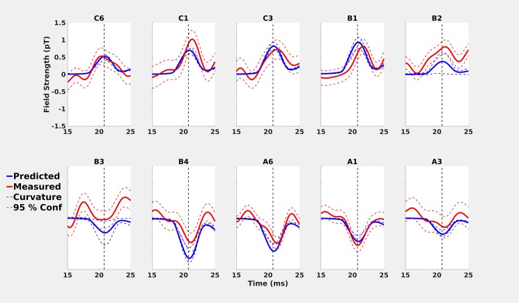
The development of new magnetic sensor technologies that promise sensitivities approaching that of conventional MEG technology while operating at far lower operating temperatures has catalysed the growing field of on-scalp MEG. The feasibility of on-scalp MEG has been demonstrated via benchmarking of new sensor technologies performing neuromagnetic recordings in close proximity to the head surface against state-of-the-art in-helmet MEG sensor technology. However, earlier work has provided little information about how these two approaches compare, or about the reliability of observed differences. Herein, we present such a comparison, based on recordings of the N20m component of the somatosensory evoked field as elicited by electric median nerve stimulation. As expected from the proximity differences between the on-scalp and in-helmet sensors, the magnitude of the N20m activation as recorded with the on-scalp sensor was higher than that of the in-helmet sensors. The dipole pattern of the on-scalp recordings was also more spatially confined than that of the conventional recordings. Our results furthermore revealed unexpected temporal differences in the peak of the N20m component. An analysis protocol was therefore developed for assessing the reliability of this observed difference. We used this protocol to examine our findings in terms of differences in sensor sensitivity between the two types of MEG recordings. The measurements and subsequent analysis raised attention to the fact that great care has to be taken in measuring the field close to the zero-line crossing of the dipolar field, since it is heavily dependent on the orientation of sensors. Taken together, our findings provide reliable evidence that on-scalp and in-helmet sensors measure neural sources in mostly similar ways.


Conflict of interest statement

Competing Interests: The authors have declared that no competing interests exist.

Figures

Fig 1
Fig 1. Photographs of experimental procedure.
A) The subject wearing the EEG-cap with the laminated guide. B) The subject lying on the recording bed with the cryostat in position. C) The cryostat on the wooden articulated armature.
Fig 2
Fig 2. Comparisons of predicted (blue solid lines) and measured (red solid lines) neuromagnetic field strengths for the in-helmet recordings in the “before” and “after” datasets.
Predicted values are based on a moving dipole fitted to the “after” whole-head recordings, measured values are presented with 95% confidence intervals (red dashed lines). A) Top row: “Before” recording: the values overlap and the N20m activation peak occurs at 20.8 ms. Bottom-row: “After” recording: predicted and measured values overlap again, but the N20m peak occurs slightly later (21.0 ms). B) Predicted in-helmet field topography and selected sensor positions.
Fig 3
Fig 3. Comparisons of predicted (solid blue lines) and measured (solid red lines) values for on-scalp recordings.
All predicted values are based on a moving dipole fitted to the whole-head “after” recording that was performed immediately after the ten on-scalp positions. Measured values include 95% confidence intervals (red dashed lines). A) On-scalp comparisons for all ten recording positions. The vertical dashed line is the estimated peak of 21.0 ms. B) predicted on-scalp topography of the neuromagnetic field for the time point with the lowest residual variance (20.8 ms). Measurement points are marked with circles. From left to right they are: C6, C1, C3, B1, B2, B3, B4, A6, A1 and A3 (same order as in A)) C) Spatial distribution of the predicted and measured values at specific time points.
Fig 4
Fig 4. Comparing the “before” and “after” recordings to assess habituation effects.
A: Topographies based on the fitted dipoles were very similar. Measurement points are marked with circles. From left to right they are. C6, C1, C3, B1, B2, B3, B4, A6, A1 and A3 (same order as in A) B: The fitted dipoles shown on cortex. C: Only minor differences were found in peak amplitudes. The peak for the “after” recording occurred 0.2 ms after the “before” recording.
Fig 5
Fig 5. Repositioning analyses.
A: Comparisons of predicted on-scalp topographies for the whole-head recordings for the repositioning (1–5). B: The estimated dipoles are temporally stable across the repositionings. C: The maximum distance between estimated dipoles was maximally ~2 mm across the repositionings.
Fig 6
Fig 6
A-D: Comparisons of different head models for the “after” recording for position A1. Single sphere models (C & D) do not result in a smoothly-varying dipole field pattern. Single shell models, however (A & B) show very similar estimations of the magnetic field generated by the source underlying N20m. The full rank model is less stable than the reduced rank model, which also shows some temporal discontinuities, e.g., before the peak of the N20m activation. E-H: Residual variance for the models.
Fig 7
Fig 7. Difference in sensitivity between position A1 and helmet sensor MEG1311.
The colouring indicates the difference in field magnitude that a source on the cortex with a current of 1 nAm would generate for the on-scalp and in-helmet sensors. Unsurprisingly, it can be seen that the on-scalp sensor is more sensitive than the in-helmet sensor for virtually every source over the target region. The magnitude of that difference, however, is manifested in a spatially heterogeneous manner. Note that similar maps showcasing spatial heterogeneity can be made between any position and any helmet sensor.
Fig 8
Fig 8. Comparisons of predicted (solid blue lines) and measured (solid red lines) values for on-scalp recordings with confidence intervals estimated by changing the orientation of the on-scalp sensor.
The orientation bounds are based on the maximal uncertainty due to the curvature of the head and the size of the cryostat lid.

References

    1. Ahonen AI, Hämäläinen MS, Kajola MJ, Knuutila JET, Laine PP, Lounasmaa OV, et al. 122-channel squid instrument for investigating the magnetic signals from the human brain. Phys Scr. 1993;1993: 198 doi: 10.1088/0031-8949/1993/T49A/033 - DOI
    1. Hämäläinen MS, Hari R, Ilmoniemi RJ, Knuutila J, Lounasmaa OV. Magnetoencephalography—theory, instrumentation, and applications to noninvasive studies of the working human brain. Rev Mod Phys. 1993;65: 413–497. doi: 10.1103/RevModPhys.65.413 - DOI
    1. Romani GL, Gratta CD, Pizzella V. Neuromagnetism and Its Clinical Applications In: Weinstock H, editor. SQUID Sensors: Fundamentals, Fabrication and Applications. Springer; Netherlands; 1996. pp. 445–490. doi: 10.1007/978-94-011-5674-5_11 - DOI
    1. Vrba J. Squid Gradiometers in Real Environments In: Weinstock H, editor. SQUID Sensors: Fundamentals, Fabrication and Applications. Springer; Netherlands; 1996. pp. 117–178. 10.1007/978-94-011-5674-5_3
    1. Heiden C. SQUID and SQUID system developments for biomagnetic applications. Clin Phys Physiol Meas Off J Hosp Phys Assoc Dtsch Ges Med Phys Eur Fed Organ Med Phys. 1991;12 Suppl B: 67–73. - PubMed

Publication types

MeSH terms