. 2017 Jul 26;7(1):6582.
doi: 10.1038/s41598-017-06391-w.

Structural and physical determinants of the proboscis-sucking pump complex in the evolution of fluid-feeding insects

Affiliations

Structural and physical determinants of the proboscis-sucking pump complex in the evolution of fluid-feeding insects

Konstantin G Kornev et al. Sci Rep. .

Abstract

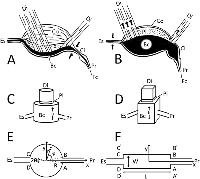
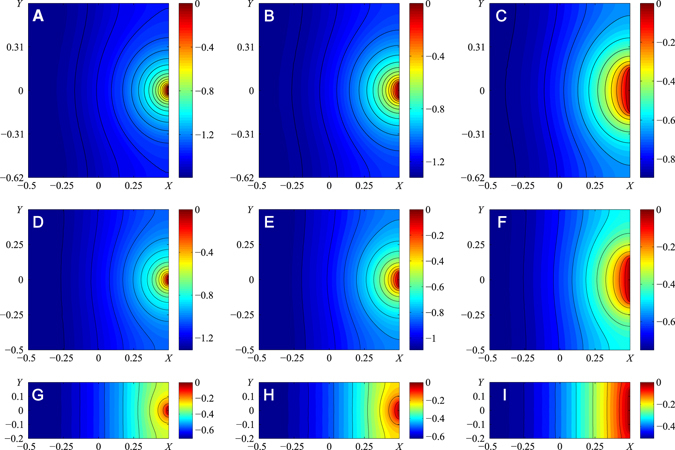
Fluid-feeding insects have evolved a unique strategy to distribute the labor between a liquid-acquisition device (proboscis) and a sucking pump. We theoretically examined physical constraints associated with coupling of the proboscis and sucking pump into a united functional organ. Classification of fluid feeders with respect to the mechanism of energy dissipation is given by using only two dimensionless parameters that depend on the length and diameter of the proboscis food canal, maximum expansion of the sucking pump chamber, and chamber size. Five species of Lepidoptera - White-headed prominent moth (Symmerista albifrons), White-dotted prominent moth (Nadata gibosa), Monarch butterfly (Danaus plexippus), Carolina sphinx moth (Manduca sexta), and Death's head sphinx moth (Acherontia atropos) - were used to illustrate this classification. The results provide a rationale for categorizing fluid-feeding insects into two groups, depending on whether muscular energy is spent on moving fluid through the proboscis or through the pump. These findings are relevant to understanding energetic costs of evolutionary elaboration and reduction of the mouthparts and insect diversification through development of new habits by fluid-feeding insects in general and by Lepidoptera in particular.


Conflict of interest statement

The authors declare that they have no competing interests.

Figures

Figure 1
Figure 1
Micro-CT images of Nadata gibosa, showing relative position of the sucking pump in the head. (A) Lateral view. (B) Dorsal view. (C) Anterior view. An, antenna; Bu, buccal chamber; Ci, cibarium; Co, compressor; Di, dilator muscles; Es, esophagus; Pa, labial palp; Pr, proboscis.
Figure 2
Figure 2
Scanning electron micrographs of moth proboscises representing various lengths: short, intermediate, and long. (A,B) Symmerista albifrons, anterior and medial views, respectively. (C,D) Nadata gibosa, lateral and apicolateral views, respectively, (E,F) Manduca sexta, lateral and apicolateral views, respectively. In (CF), the galeae have been separated apically to show the food canal (fc) and dorsal legulae (dl).
Figure 3
Figure 3
Schematic of lepidopteran sucking pump. (A,B) Lateral view of the sucking pump, consisting of the buccal chamber (Bc) and cibarium (Ci). Flow of liquid is from right to left, through the food canal (Fc) of the proboscis (Pr), into the sucking pump (Ci and Bc), and exiting via the esophagus (Es). Arrows indicate direction of muscle contraction. In (A), the dilator muscles (Di) have relaxed and the compressor muscle (Co) of the pump has contracted, forcing the plunger (Pl) toward the chamber floor. In (B), the compressor muscle of the pump has relaxed and the dilator muscles (Di) have contracted, drawing the plunger toward the dorsum of the buccal chamber. (CF) Models of the sucking pump (not to scale). (C) The Daniel-Kingsolver model of a sucking pump. The buccal chamber is modeled as a cylindrical chamber and the circular plunger fits the chamber firmly. When the plunger moves in the vertical direction, it changes the expansion h. The proboscis and esophagus are attached to the buccal chamber. (D) The Bennet-Clark model of a sucking pump. The buccal chamber is modeled as a rectangular box and the plunger fits the box firmly. When the plunger moves in the vertical direction, it changes the expansion h. The proboscis and esophagus are attached to the buccal chamber. (E) Cirular (radius R) lengthwise cross-section of a model pump. Ratio AB/R is equal to 2θ. The model pump has opening AB connecting the chamber with the proboscis and opening CD connecting the chamber with the esophagus. (F) Rectangular lengthwise cross-section of width W and length L of a model pump. Any point on the chamber floor can be specified by either Cartesian coordinates (x,y) for rectangular U-chambers or by cylindrical coordinates (r,φ) for circular U-chambers.
Figure 4
Figure 4
Example of FEM mesh used for pressure calculations. Each triangular finite element provides three pressure values associated with three nodes. The nodes are concentrated in the vicinity of points A and B where boundary conditions change. In this example, opening AB was 2θ = 2π/5, and 25 refinements were used. Dense nodes indicate high pressure gradients, whereas sparse nodes indicate lower gradients.
Figure 5
Figure 5
(AI) Dimensionless pressure distribution PK r for three different sizes of food canal diameter to chamber length ratios |AB|/L and three different sizes of chamber elongations W/L. Parameter W/L is equal to (1.24, 1, 0.4) for the three rows from top to bottom, and parameter |AB|/L is equal to (0.05, 0.1, 0.3) for the three columns from left to right. The color bar sets the pressure level. Black lines indicate constant pressure; the two nearest lines have a dimensionless pressure difference of 0.08.
Figure 6
Figure 6
Dimensionless pressure distribution P − K c for different ratios of the food canal diameter |AB| to chamber diameter 2 R. (A) |AB|/(2R) = 0.05, (B) |AB|/(2R) = 0.01, (C) |AB|/(2R) = θ = 0.15, (D) |AB|/(2 R) = 0.3, (E) |AB|/(2R) = θ = 0.6, (F) |AB|/(2R) = θ = 0.78. The color bar sets the pressure level. Black lines indicate constant pressure; the two nearest lines have a dimensionless pressure difference of 0.2.
Figure 7
Figure 7
Dependence of constants C r and C c on size of pump openings |AB|/L and |AB|/2 R, respectively. (A) Rectangular chamber, dependence of C r on |AB|/L for different W/L. The arrow indicates direction of increase of the W/L ratio, with uniform steps of 0.5, starting from 0.5 and ending at 2. Circles at the end of each curve correspond to limiting cases of pumps with W = AB. (B) Circular chamber, with dependence of C c on θ = |AB|/(2 R); it tends to zero as θ → π. Dashed line is an empirical approximation of this dependence as C c = 3.1 ln θ − 2.25.
Figure 8
Figure 8
Classification of the pump–proboscis pair with respect to energy dissipation mechanisms. The sequence of curves is the same as that in Fig. 7. The red curve indicates a circular pump, and the black curves indicate rectangular pumps. All parameters used to calculate these black curves are identical to those in the caption of Fig. 7.

References

    1. Chapman, R. F. The Insects: Structure and Function, 4th edition (Cambridge University Press, 1998).
    1. Kingsolver, J. G. & Daniel, T. L. Mechanics of food handling by fluid-feeding insects in Regulatory Mechanisms in Insect Feeding (eds. Chapman, R. F. & de Boer, G.) 32–74 (Springer, 1995).
    1. Labandeira CC. Insect mouthparts: ascertaining the paleobiology of insect feeding strategies. Annu. Rev. Ecol. Syst. 1997;28:153–193. doi: 10.1146/annurev.ecolsys.28.1.153. - DOI
    1. Labandeira CC. The pollination of mid Mesozoic plants and the early history of long-proboscid insects. Ann. Missouri Bot. Gard. 2010;97:469–513. doi: 10.3417/2010037. - DOI
    1. Misof B, et al. Phylogenomics resolves the timing and pattern of insect evolution. Science. 2014;346:763–767. doi: 10.1126/science.1257570. - DOI - PubMed

Publication types

LinkOut - more resources