An Easy to Manufacture Micro Gas Preconcentrator for Chemical Sensing Applications
- PMID: 28753000
- PMCID: PMC6541441
- DOI: 10.1021/acssensors.7b00289
An Easy to Manufacture Micro Gas Preconcentrator for Chemical Sensing Applications
Abstract
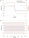
We have developed a simple-to-manufacture microfabricated gas preconcentrator for MEMS-based chemical sensing applications. Cavities and microfluidic channels were created using a wet etch process with hydrofluoric acid, portions of which can be performed outside of a cleanroom, instead of the more common deep reactive ion etch process. The integrated heater and resistance temperature detectors (RTDs) were created with a photolithography-free technique enabled by laser etching. With only 28 V DC (0.1 A), a maximum heating rate of 17.6 °C/s was observed. Adsorption and desorption flow parameters were optimized to be 90 SCCM and 25 SCCM, respectively, for a multicomponent gas mixture. Under testing conditions using Tenax TA sorbent, the device was capable of measuring analytes down to 22 ppb with only a 2 min sample loading time using a gas chromatograph with a flame ionization detector. Two separate devices were compared by measuring the same chemical mixture; both devices yielded similar peak areas and widths (fwhm: 0.032-0.033 min), suggesting reproducibility between devices.
Keywords: chemical sensor; detectors; gas preconcentrator; microelectromechanical systems (MEMS); sorbent.
Conflict of interest statement
CONFLICT OF INTEREST DISCLOSURE
The authors declare that a patent application has been submitted on part of the work presented in this paper.
Figures


References
-
- Voiculescu I; Zaghloul M; Narasimhan N, Microfabricated chemical preconcentrators for gas-phase microanalytical detection systems. TrAC Trends in Analytical Chemistry 2008, 27 (4), 327–343.
-
- Lu CJ; Steinecker WH; Tian WC; Oborny MC; Nichols JM; Agah M; Potkay JA; Chan HKL; Driscoll J; Sacks RD; Wise KD; Pang SW; Zellers ET, First-generation hybrid MEMS gas chromatograph. Lab Chip 2005, 5 (10), 1123–1131. - PubMed
-
- James F; Breuil P; Pijolat C; Camara M; Briand D; Bart A; Cozic R, Development of a MEMS Preconcentrator for Micro-gas Chromatography Analyses. Procedia Engineering 2014, 87, 500–503.
-
- Terry SC; Jerman JH; Angell JB, A gas chromatographic air analyzer fabricated on a silicon wafer. IEEE Transactions on Electron Devices 1979, 26 (12), 1880–1886.
-
- Zarejan-Jahromi MA; Ashraf-Khorassani M; Taylor LT; Agah M, Design, Modeling, and Fabrication of MEMS-Based Multicapillary Gas Chromatographic Columns. J Microelectromech S 2009, 18 (1), 28–37.
Grants and funding
LinkOut - more resources
Full Text Sources
Other Literature Sources

