. 2017 Aug 9;117(15):10212-10290.
doi: 10.1021/acs.chemrev.7b00074. Epub 2017 Jul 30.

Polymers for 3D Printing and Customized Additive Manufacturing

Affiliations

Polymers for 3D Printing and Customized Additive Manufacturing

Samuel Clark Ligon et al. Chem Rev. .

Abstract

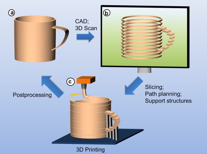
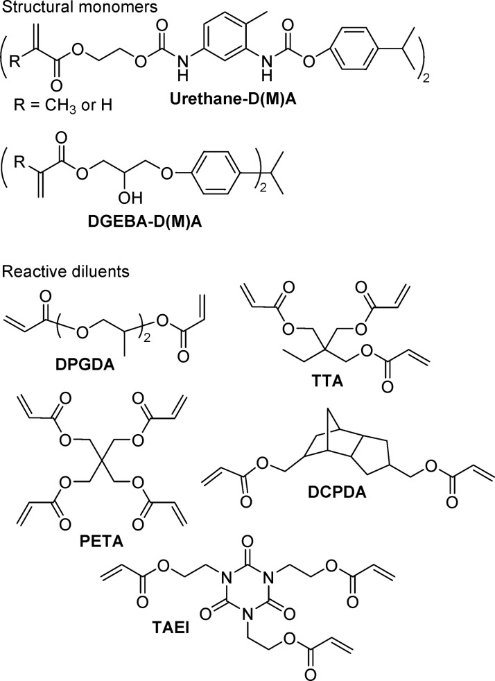
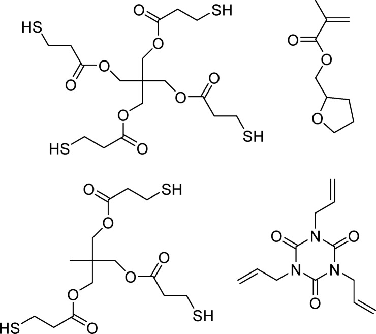
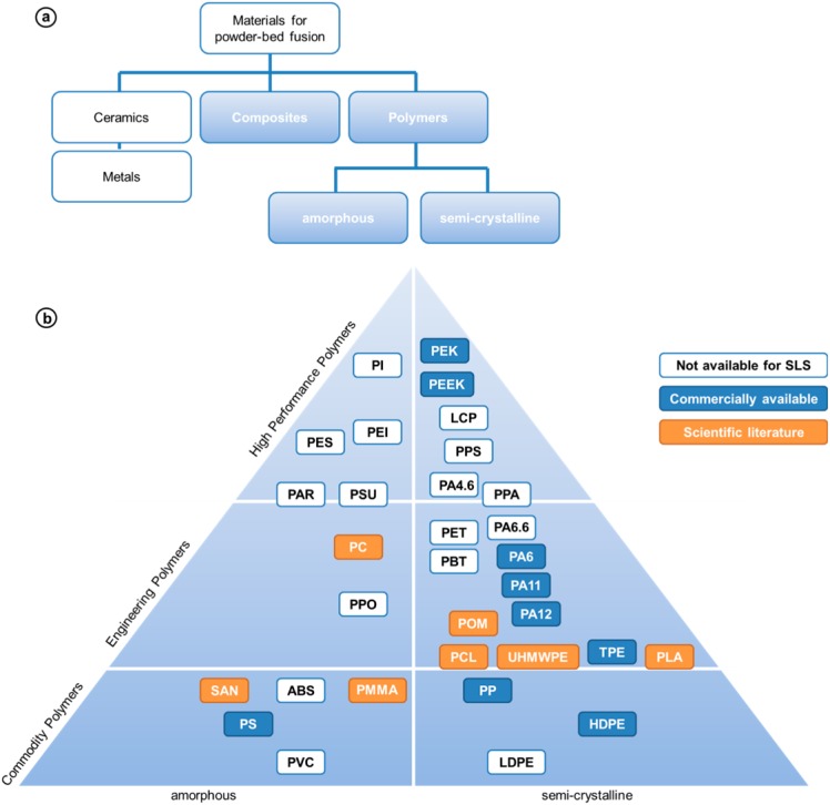
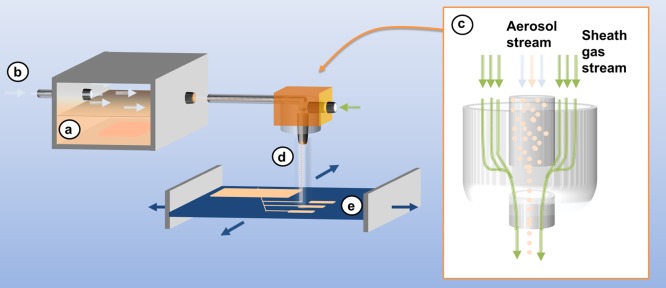
Additive manufacturing (AM) alias 3D printing translates computer-aided design (CAD) virtual 3D models into physical objects. By digital slicing of CAD, 3D scan, or tomography data, AM builds objects layer by layer without the need for molds or machining. AM enables decentralized fabrication of customized objects on demand by exploiting digital information storage and retrieval via the Internet. The ongoing transition from rapid prototyping to rapid manufacturing prompts new challenges for mechanical engineers and materials scientists alike. Because polymers are by far the most utilized class of materials for AM, this Review focuses on polymer processing and the development of polymers and advanced polymer systems specifically for AM. AM techniques covered include vat photopolymerization (stereolithography), powder bed fusion (SLS), material and binder jetting (inkjet and aerosol 3D printing), sheet lamination (LOM), extrusion (FDM, 3D dispensing, 3D fiber deposition, and 3D plotting), and 3D bioprinting. The range of polymers used in AM encompasses thermoplastics, thermosets, elastomers, hydrogels, functional polymers, polymer blends, composites, and biological systems. Aspects of polymer design, additives, and processing parameters as they relate to enhancing build speed and improving accuracy, functionality, surface finish, stability, mechanical properties, and porosity are addressed. Selected applications demonstrate how polymer-based AM is being exploited in lightweight engineering, architecture, food processing, optics, energy technology, dentistry, drug delivery, and personalized medicine. Unparalleled by metals and ceramics, polymer-based AM plays a key role in the emerging AM of advanced multifunctional and multimaterial systems including living biological systems as well as life-like synthetic systems.


Conflict of interest statement

The authors declare no competing financial interest.

Figures

Figure 1
Figure 1
Basic principles of additive manufacturing. (a) Development of product idea that is transformed into digital data by means of CAD, or analysis of geometric data by means of 3D scanning; (b) preprocessing of model data: slicing of virtual model into layered data, adjustment of support structures to stabilize craning structures, path planning, and successive transfer of layered data to 3D printer; (c) and additive manufacturing of model or product, for example, by melt extrusion, postprocessing to remove typical artifacts including support structures and surface roughness due to staircase effects.
Figure 2
Figure 2
Comparison of (a) subtractive, (b) additive, and (c) formative manufacturing techniques.
Figure 3
Figure 3
Research interest in rapid prototyping, 3D printing, additive manufacturing and bioprinting, as indicated by the number of hits per annum for the respective terms (data from Web of Science, accessed July 27, 2017).
Figure 4
Figure 4
Worldwide revenues from AM products and services between 1995 and 2016. Data from ref (12).
Figure 5
Figure 5
Worldwide revenues from AM material sales between 2000 and 2016. Data from ref (12).
Figure 6
Figure 6
Image from U.S. Patent 4575330 introducing the term and the concept of stereolithography. Description of components using the numbering scheme from the patent: (21) container, (22) UV curable liquid, (23) working surface, (26) UV light source, (27) UV light spot, (28) computer, (29) movable elevator platform, (30) three-dimensional object, and (30a–c) integrated laminae of the object.
Figure 7
Figure 7
Digital light processing (DLP) consisting of (a) vat filled with photopolymer resin, (b) light source, (c) micromirror array, (d) vertically movable building platform, and (e) tilting device to replenish the uncured bottom layer.
Figure 8
Figure 8
Continuous liquid interface production (CLIP). Reprinted with permission from ref (27). Copyright 2015 the American Association for the Advancement of Science.
Figure 9
Figure 9
Simplified Jablonski diagram showing OPA and degenerate (one color) TPA excitation processes. S0 is the ground state and S1 is an excited state reached directly by OPA or indirectly by TPA via a very short-lived higher energy state (S2); ω1 and ω2 are incident light frequencies, and ω3 is a fluorescent emission frequency. Reproduced with permission from ref (74). Copyright 2008 Elsevier.
Figure 10
Figure 10
Schematic setup of MPP microfabrication. License CC BY 4.0.
Figure 11
Figure 11
Relation between laser intensity, voxel size, and success of polymerization. Reproduced with permission from ref (95). Copyright 2008 Cuvillier Verlag.
Figure 12
Figure 12
Jablonski diagram of STED for 2PP. Reproduced with permission from ref (105). Copyright 2014 Royal Society of Chemistry.
Scheme 1
Scheme 1. Norrish Type I Photocleavage of Darocur 1173
Figure 13
Figure 13
Type I radical photoinitiators commonly cited in stereolithography patents.
Scheme 2
Scheme 2. Radical Generation from Type II Photoinitiators
Figure 14
Figure 14
Meth(acrylate) monomers for AM.
Scheme 3
Scheme 3. Thiol–Ene Reactions
Scheme 4
Scheme 4. Network Formation with Thiol–Ene Monomers versus Network Formation with Acrylate Monomers
Adapted with permission from ref (146). Copyright 2016 the Royal Society of Chemistry.
Figure 15
Figure 15
Thiol–ene components in commercial photocurable resins.
Figure 16
Figure 16
β-Allyl sulfone AFCT reagents (MAS and DAS) and sulfone ester AFCT reagent (VSE).
Figure 17
Figure 17
Mechanical properties of dimethacrylate polymers with 20 wt % thiol additive (DT) and with 20 wt % AFCT reagent (DAS). Reprinted with permission from ref (155). Copyright 2015 Royal Society of Chemistry.
Figure 18
Figure 18
Representative cationic photoinitiators and a schematic for generation of the primary initiating species.
Figure 19
Figure 19
Epoxide monomers and polyol chain extenders for cationic photopolymerization.
Scheme 5
Scheme 5. Cationic Chain Growth of Diepoxide Monomers and Chain Transfer with Diols
Figure 20
Figure 20
Vinyl ether and oxetane monomers commonly cited in SLA patents.
Figure 21
Figure 21
Hybrid (meth)acrylate/epoxy monomers from patent literature and commercially available.
Figure 22
Figure 22
TPA photoinitiators with TPA cross-section (σTPA).
Figure 23
Figure 23
Schematics of different TPA chromophores classified by substitution pattern (D = electron donor, π = π-conjugated bridge, A = acceptor moiety).
Scheme 6
Scheme 6. Evolution of Multipolar Chromophores from Stilbene
Figure 24
Figure 24
Intra- and intermolecular transfer process of common 2PP initiators from literature.
Figure 25
Figure 25
(a) Submicrometer mesh structures for qualitative assessment of TPA initiators and (b) 3D plot of double bond conversion versus laser power and scanning speed. Reprinted with permission from refs (201) and (202). Copyrights 2011 Wiley and 2011 AIP Publishing LLC, respectively.
Figure 26
Figure 26
(a–c) Microscopic replicas of real-world objects created via 2PP. Reproduced with permission from refs (201) and (204). Copyrights 2011 Wiley (a,b) and 2012 TU Wien (c).
Figure 27
Figure 27
(a) Two-photon PAG (BSB-S2) and (b) 3D microstructures constructed in SU-8 resin. Reproduced with permission from ref (206). Copyright 2003 Elsevier Ltd.
Figure 28
Figure 28
Stabilizers and light absorbers for AM photoresins.
Figure 29
Figure 29
Sacrificial molding with water-soluble photopolymers.
Figure 30
Figure 30
AM produced ceramic functional parts from Lithoz GmbH. The turbine wheel diameter is 10 mm.
Figure 31
Figure 31
Siloxane (meth)acrylate monomers and oligomers for lithographic fabrication of ORMOCER materials.
Figure 32
Figure 32
(Selective) laser sintering process comprised of (a) vertically movable build platform, (b) powder bed with embedded, sintered model layers, (c) laser source and (d) laser optics, (e) powder feedstock and deposition hopper, and (f) blade for powder distribution and leveling.
Figure 33
Figure 33
Bionic handling assistant produced by laser sintering (image courtesy of EOS GmbH/Festo AG & Co. KG). The gripping tool can reliably pick up and gently put down objects (part manufactured with PA-12 powder).
Figure 34
Figure 34
Powder and process parameters influencing properties of polymer parts produced by SLS. Reprinted with permission from ref (252). Copyright 2014 Cambridge University Press.
Figure 35
Figure 35
DSC curves of commercial semicrystalline powders for SLS. Black, PA-12 powder fabricated by precipitation from ethanol solution (PA2200; EOS GmbH); red, PA-11 powder fabricated by cryogenic grinding (PA1100; EOS GmbH).
Figure 36
Figure 36
DSC curve of commercial amorphous powder for SLS (PrimeCast 101 polystyrene powder; EOS GmbH).
Figure 37
Figure 37
Fabrication of polymeric SLS powders: (a) precipitation from polymer solution; (b) coextrusion of polymer solution with immiscible solvent; (c) emulsion polymerization of water-insoluble monomers; (d) spray drying of polymer solution; (e) cryogenic milling of polymer powders; and (f) SLS processing of powders with controlled size distribution and formulated additives.
Figure 38
Figure 38
Morphology of commercial powders for polymer laser sintering. (a) Cryogenically ground, rough particles (PA-11 powder PA1101 from EOS GmbH); (b) potato-shaped particles precipitated from ethanol solution (PA-12 powder PA2200 from EOS GmbH); and (c) spherical particles produced by means of emulsion polymerization (PS powder PrimeCast 101 from EOS GmbH).
Figure 39
Figure 39
PEEK/PA-12 blend powder particles produced by mechanical alloying during cryogenic milling. (a) Schematic sketch of the two-phase lamellar microstructure of powder particles produced by cryogenic milling. Reprinted with permission from ref (294). Copyright 1990 Springer International Publishing AG. (b) SEM micrograph of PEEK/PA-12 powder particle illustrating an irregular, rough particle shape and the absence of discernible PEEK and PA-12 domains. Reprinted with permission from ref (293). Copyright 2000 R. G. Kander.
Figure 40
Figure 40
Classification of materials for SLS additive manufacturing (a) according to inorganic or polymeric content; and (b) according to the so-called pyramid of polymeric materials.
Figure 41
Figure 41
Stiffness/toughness-balance of commercial SLS materials. Mechanical properties (Young’s modulus and elongation at break) are based on technical information provided by the respective material suppliers.
Figure 42
Figure 42
PolyJet process (from Stratasys) consisting of (a) vertically movable building platform, (b) multinozzle inkjet head, (c) layers of support material, (d) layers of building material, and (e) UV source attached to inkjet head.
Figure 43
Figure 43
Aerosol jet printing process by OPTOMEC Inc. comprised of (a) aerosol chamber equipped with ultrasonification atomizer, (b) inert gas inlet enabling transport of aerosol to vertically movable print head (c), equipped with nozzles for aerosol deposition and for creating annular sheath gas stream (d) to focus aerosol jet onto (a) horizontally movable building platform.
Figure 44
Figure 44
High aspect ratio 3D structures produced by aerosol jet printing of an acrylic resin in conjunction with simultaneous UV LED curing. (a,b) Array of pillar structures with height = 1.0 mm, height variation = 1%, spacing = 0.5 mm, diameter = 90 μm. (c) Spiral structure and (d) corresponding topography as determined by line scan. Images courtesy of OPTOMEC Inc.
Figure 45
Figure 45
3DP comprised of (a) vertically movable build platform, (b) printed model embedded in supporting powder bed, (c) inkjet printing head for deposition of binder material, (d) support material feed stock, and (e) roller for powder distribution and leveling.
Figure 46
Figure 46
Classification of powder/ink combinations used in 3DP.
Figure 47
Figure 47
Laminated object modeling process comprised of (a) vertically movable build platform, (b) material feedstock containing sheet rolls, (c) residual material collection, (d) CO2 laser, and (e) laser optics cutting layer contours and crosshatch pattern.
Figure 48
Figure 48
Fused deposition modeling process invented by Scott Crump at Stratasys, Inc., comprises of (a) a vertically movable building platform, and (b) a tempered extrusion printing head for deposition of (c) model and (d) support material stored in (e) feedstocks containing filaments of thermoplastics wound on a spool.
Figure 49
Figure 49
First self-replication of a machine using open source RepRap AM by Adrian Bowyer (left). Image license CC BY-SA 3.0.
Figure 50
Figure 50
3D micro extrusion alias 3D dispensing and 3D plotting comprised of (a) a building platform in air or immersed in a liquid, and (b) a dispenser nozzle attached to a (c) 3D movable extrusion head, which can be heated.
Figure 51
Figure 51
Principle of zero-gravity 3D dispensing in the absence of temporary support structures exploiting the Archimedes principle: (a) 3D-dispensing in a liquid by matching its density with that of dispensed material stabilizes delicate structures as gravity is compensated by buoyancy; and (b) by comparison, 3D dispensing in air would lead to structural collapse due to gravity-induced flow prior to solidification. In view of its prospects for biofabrication in aqueous media, zero-gravity 3D dispensing is also named 3D bioplotting.
Figure 52
Figure 52
Alginate hydrogel scaffold fabricated by means of reactive 3D dispensing of water-soluble sodium alginate in water containing Ca2+ ions, which cross-link alginate by cation exchange producing water-insoluble calcium alginate hydrogels.
Figure 53
Figure 53
Materials and applications of 3D bioplotting.
Figure 54
Figure 54
Water-induced transformation of a 4D printed linear strand of two different polymers, which self-assemble to a cube. Reproduced with permission from ref (538). Copyright 2014 Wiley and Sons.
Figure 55
Figure 55
Thermally responsive multimaterial 4D printed gripper. The lower images are a time-lapsed series demonstrating the grabbing of an object. Image license CC BY 4.0.
Figure 56
Figure 56
Use of AM based on industrial sector. Data from ref (297).
Figure 57
Figure 57
Most common applications for AM. Data from ref (297).
Figure 58
Figure 58
Customized neurosurgical guide manufactured by SLS with PA-12 powder (image courtesy of EOS GmbH/FHC, Inc.).
Figure 59
Figure 59
Invisalign from Align Technology. On the right, the internal view presents bite ramps on the lingual surface of the upper aligner. Images courtesy of Align Technology.
Figure 60
Figure 60
Growth and mineralization of bone structure on PCL scaffold implanted into mice according to (a–d) μCT scans and (e) histological staining. Reprinted with permission from ref (270). Copyright 2005 Elsevier B.V.
Figure 61
Figure 61
PCL scaffolds for tissue engineering applications. Viability of chondrocytes in pristine PCL scaffold (PCL), gelatin-modified scaffold (GEL+P), and collagen-modified scaffold (COL+P) using the live/dead assay with a confocal microscope. Top row, week 2; bottom row, week 4. Scale bar = 300 μm. Reprinted with permission from ref (586). Copyright 2014 Elsevier B.V.
Figure 62
Figure 62
Comparative hydrolysis of acrylate-based polymers and polymers from acrylate alternatives. Degradation of cross-linked polymers is depicted on the left, while that of unreacted functional groups is on the right.
Figure 63
Figure 63
Water-soluble photoinitiators for lithographic hydrogel fabrication: (a) Irgacure 2959, (b) lithium phenyl-2,4,6-trimethylbenzoylphosphinate, (c) Eosin Y and (d) Rose Bengal.
Figure 64
Figure 64
C. elegans captured in a woodpile structure with 200 μm side length (line distance 4 μm, layer distance 3.5 μm, 10 layers, writing speed 10 mm s–1, laser power 220 mW, 50% water content): (a) LSM image 20×, (b) detail of white boxed section in (a), LSM image 50×, (c) stacked 3D LSM image 20×, and (d) water-soluble photoinitiator (WSPI) used. License CC BY 4.0.
Figure 65
Figure 65
Hydrogel formation via thiol–ene click chemistry using reduced bovine serum albumin (BSA) and vinyl ester modified gelatin. Reproduced with permission from ref (633). Copyright 2013 Wiley.
Figure 66
Figure 66
Cell density distributions on (a) conventional scaffolds where cells are seeded onto the scaffold surface versus (b) integrating cells into AM fabrication of hydrogels.
Figure 67
Figure 67
Knee meniscus construct designed from a patient MRI and bioprinted on a 3D Bioplotter using an alginate-nanofiber/human stem cell bioink. Reproduced with permission from ref (655). Copyright 2016 American Chemical Society.
Figure 68
Figure 68
Scanning electron micrographs of ORMOCER microneedles with (a) 0 μm, (b) 1.4 μm, and (c) 20.4 μm pore-needle center displacement values. Reprinted with permission from ref (716). Copyright 2007 John Wiley and Sons.
Figure 69
Figure 69
Edible structure by AM of paste based on insect proteins. Reprinted with permission from ref (728). Copyright 2012 Elsevier B.V.
Figure 70
Figure 70
Sugar sculpture produced by means of SLS (CandyFab Sugar Printing; image by Windell H. Oskay). License CC BY 2.0.
Figure 71
Figure 71
Principle of a microring resonator (top) based on 2PP and fabricated waveguide structures (bottom). Reproduced with permission from ref (748). Copyright 2008 Wiley-VCH Verlag GmbH & Co. KGaA.
Figure 72
Figure 72
(a) Cross-section of an optical waveguide bundle fabricated in PDMS swollen with acrylate monomer and selectively cross-linked by. (b) Phase contrast image of a series of PDMS/acrylate waveguides cured with increasing laser power.
Figure 73
Figure 73
SEM image of a Zr-based photonic crystal structure. Reproduced with permission from ref (106). Copyright 2008 A. Ovsianikov et al.
Figure 74
Figure 74
Optical images of a triangular honeycomb structure composed of SiC/C-filled epoxy, which reveal highly aligned carbon fibers oriented along the print direction. Images b and c are excerpts from image a as the white rectangles indicate. The scale bar in (c) is 500 μm. Reproduced with permission from ref (765). Copyright 2014 John Wiley and Sons.
Figure 75
Figure 75
3D printed interdigitated electrodes. The anode is a composite of lithium titanium oxide/graphene oxide, and the cathode is lithium iron phosphate/graphene oxide. Reproduced with permission from ref (782). Copyright 2016 John Wiley and Sons.
Figure 76
Figure 76
A 3D-drawing with the hand-held 3D Sunlu extruder (image courtesy of Benjamin Stolz and Fan Zhong of the Freiburg Materials Research Center, FMF).
Figure 77
Figure 77
3D printing furniture from recycled ABS. Image reproduced with permission from Dirk Vander Kooij.
Figure 78
Figure 78
Flexible textiles by AM. Left and center: The Kinematics Dress 6 from Nervous System (dress designed by Jessica Rosenkrantz and Jesse Louis-Rosenberg; photos by Steve Marsel Studio; images reproduced with permission from Nervous System). Right: Weft knitted PA-12 textile produced by SLS. License CC BY 3.0.
Figure 79
Figure 79
Top: 3D printed house fabricated via D-shape process. Image reproduced with permission from ref (810). Copyright 2014 Elsevier. Bottom: Concrete printer from Apis-Cor for on-site construction. Image courtesy of www.3ders.org.

References

    1. Gebhardt A.Rapid Prototyping; Hanser Verlag: Munich, DE, 2003.
    1. ASTM International - Standards Worldwide; http://www.astm.org/ (accessed Mar 25, 2014).
    1. ASTM F2792-12a. Standard Terminology for Additive Manufacturing Technologies; ASTM International: West Conshohocken, PA, 2012.
    1. Jacobs P. F.Stereolithography and Other RP&M Technologies - from Rapid Prototyping to Rapid Tooling; SME Publications: Dearborn, MI, 1996.
    1. Jacobs P. F.; Reid D. T.. Rapid Prototyping & Manufacturing: Fundamentals of Stereolithography; Society of Manufacturing Engineers: Dearborn, MI, 1992.