Review
. 2017 Sep 15;57(9):435-460.
doi: 10.2176/nmc.ra.2017-0032. Epub 2017 Aug 1.

Pediatric Craniovertebral Junction Surgery

Affiliations
Review

Pediatric Craniovertebral Junction Surgery

Nobuhito Morota. Neurol Med Chir (Tokyo). .

Abstract

The craniovertebral junction (CVJ) has attracted more attention in pediatric medicine in recent years due to the progress in surgical technologies allowing a direct approach to the CVJ in children. The CVJ is the site of numerous pathologies, most originating in bone anomalies resulting from abnormal CVJ development. Before discussing the surgical approaches to CVJ, three points should be borne in mind: first, that developmental anatomy demonstrates age-dependent mechanisms and the pathophysiology of pediatric CVJ anomalies; second, that CT-based dynamic simulations have improved our knowledge of functional anatomy, enabling us to locate CVJ lesions with greater certainty; and third, understanding the complex structure of the pediatric CVJ also clarifies the surgical anatomy. This review begins with a description of the embryonic developmental process of the CVJ, comprising ossification and resegmentation of the somite. From the clinical perspective, pediatric CVJ lesions can be divided into three categories: developmental bony anomalies with or without instability, stenotic CVJ lesions, and others. After discussing surgery and management based on this classification, the author describes surgical outcomes on his hands, and finally proceeds to address controversial issues specific for pediatric CVJ surgery. The lessons, which the author has gleaned from his experience in pediatric CVJ surgery, are also presented briefly in this review. Recent technological progress has facilitated pediatric surgery of the CVJ. However, it is important to recognize that we are still far from reliably and consistently obtaining satisfactory results. Further progress in this area awaits contributions of the coming generations of pediatric surgeons.

Keywords: congenital anomaly; craniovertebral junction; embryology; pediatrics; surgery.


Conflict of interest statement

Conflicts of Interest Disclosure

The author has no conflicts of interest regarding this manuscript and has registered online Self-reported COI Disclosure Statement Forms through the website for the Japan Neurosurgical Society (JNS) members.

Figures

Fig. 1
Fig. 1
Diagnosis and surgical procedures in 108 children who received CVJ surgery. (CM1: Chiari malformation type 1, CM2: Chiari malformation type 2, AAD: Atlantoaxial dislocation).
Fig. 2
Fig. 2
Failure of separation and resegmentation of the sclerotome results in CVJ bony anomalies such as fused laminae and hemi- or split vertebrae.
Fig. 3
Fig. 3
Process of separation and resegmentation at the CVJ is shown. Note that C1 is derived from somites 5 and 6 with a supplementary role played by somite 4. C2 is composed of somites 5 to 7.
Fig. 4
Fig. 4
Ossification process of C1. C1 ossification starts at around age 6 months and is completed by age 13.
Fig. 5
Fig. 5
Ossification process of C2. C2 ossification starts at around age 3 months and is complete by age 13. The process is more complicated than that of C1.
Fig. 6
Fig. 6
Treatment algorithm for pediatric CVJ bony anomalies based on the practical classification.
Fig. 7
Fig. 7
Algorithm for the selection of surgical procedures for CVJ lesions with AAD. (CDP: chondrodysplasia punctata, OCPF: occipito-cervical posterior fusion, P.F.: posteroior fixation, UHMW-PE: ultra high molecular weight polyethylene).
Fig. 8
Fig. 8
Pre- (a–c) and postoperative (d–f) CT and MRI in a 1-year-old child with chondrodysplasia punctata. a: A 2D midsagittal CT scan reconstruction in the flexion position showed prominent dysplastic vertebral bodies from C3 to C6 causing cervical instability and kyphosis. b: Instability of cervical spine is reducible with neck extension. c: Intramedullary signal change on MR T2 weighted image. d and e: Postoperative 3D CT scan reconstruction shows the halo external fixation. Rib autograft bones were used because posterior fixation ranged from the occipital bone to C7. f: A 2D midsagittal CT scan reconstruction demonstrates improved cervical stability. The right rib autograft is absorbed at the rostral end but the left autograft forms a fibrous fusion with the occipital bone.
Fig. 9
Fig. 9
The same patient as in Fig. 8. a: Positioning of the patient in surgery. The head is held in traction using the halo ring attached to the skull. b: Intraoperative photograph showing exposure from the foramen magnum to C7. c: A pair of UHMW-PE cables at the edge of the foramen magnum, C2, C5–C6, and C7 sublaminar space. d: Rib autograft bones are fixed by tightening the UHMW-PE cable to achieve occipito-C7 posterior fusion. Right figure shows the intraoperative continuous MEP records. The MEP remained stable throughout the procedure. (APB: abductor pollicis brevis muscle, ISI: interstimulus interval)
Fig. 10
Fig. 10
Attachment of the halo head ring. a and b: The halo head ring is attached to the skull using six head pins with 2 to 3 inch-pounds torque (1/2 to 1/3 of adult pressure) or less. (*: ceramic powder was used to fill the skull defect resulting from harvesting graft bone.) c: Pin penetration into the intracranial space after tumbling and striking the floor with the halo head ring. The pin was successfully removed and the head ring was re-placed.
Fig. 11
Fig. 11
Anterior approach to the CVJ in a 16-year-old patient with Hadju-Cheny syndrome. Pre (a, b) and postoperative (c) pictures. a and b: Prominent BI with brain stem compression was observed. c: Caudal end of the clivus, C1 anterior arch, and C2 odontoid process were removed, and brain stem compression was relieved. d and e: OCPF with instruments was carried out three weeks later. Note the syringomyelia also improved postoperatively.
Fig. 12
Fig. 12
Unilateral fixation of the CVJ for a 6-year-old child with multiple anomaly syndrome. Pre (a–d) and postoperative (e–h) CT and MRI. a and b: Severe AAD associated with atlanto-axial rotatory fixation and C2–C3 dislocation caused severe CVJ stenosis with prominent cervical cord compression. c and d: CT angiographies superimposed on 3D reconstructed CVJ revealed arterioplania of the left vertebral artery. e and f: AAD reduction by head traction, C1 laminectomy, and occipito-C5 posterior fixation using unilateral instrumentation was carried out. The cervical alignment improved after surgery. g and h: Unilateral instrumentation (white arrows) and implanted rib bones (*).
Fig. 13
Fig. 13
Shape and size of the FM in achondroplasia. Circumferential stenosis can be seen. Normal FM for comparison (right). The shape of the FM in achondroplasia is oval, teardrop-shaped (left), or keyhole-shaped (middle).
Fig. 14
Fig. 14
Left: FM stenosis with CVJ compression was observed in a 10-month-old child with achondroplasia. Note the developed occipital and marginal sinuses on MR venography. The finding evokes special attention to protect dural sinuses, which could be fatal once they are damaged. Right: Postoperative CT and MRI revealed satisfactory dorso-lateral bony decompression and reduced CVJ compression.
Fig. 15
Fig. 15
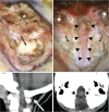
Intraoperative photographs of the child in Figure 14. Left: Exposed CVJ before decompression. The posterior margin of the FM is invisible because it is located behind the C1 lamina (black arrow) White asterisk: occipital bone. Note that the white arrow on the CT sagittal image indicates the orientation of the photo. Right: The CVJ after decompression. Black triangles: outer layer of the dura incised for duraplasty. Black arrows: fibrous band at the FM. White stars: ventral end of the drilled FM, corresponding to the black stars on the CT axial image below. Note: posterior half of the FM is decompressed.
Fig. 16
Fig. 16
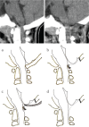
CVJ decompression in achondroplasia: Upper row shows pre and postoperative CT midsagittal images. Lower row demonstrates process of CVJ in achondroplasia. a: Before CVJ decompression. b: Suboccipital small craniectomy, first. Rim of the FM is left. c: C1 laminectomy, next. The dura over the cerebellar hemisphere would be retracted to secure surgical field. Then, the rim of the FM is removed and decompression extends to the lateral side. d: After CVJ decompression.
Fig. 17
Fig. 17
Algorithm for selecting surgical procedure in CM1. (N.D.: neurological deficit, ETV: endoscopic third ventriculostomy)
Fig. 18
Fig. 18
Surgery of a 3-year-old child with CM1.5. Left: Intraoperartive photographs. Herniated tonsils extending below C2 were pulled out and coagulated to secure the subarachnoid space on the midline. The obex is exposed and opened if covered with a membrane. In this case, the membrane called “arachnoid veil” was absent. Right: Pre- and postoperative CT and MRI. Note: suboccipital craniectomy is limited in size but sufficient for decompression on the midline.
Fig. 19
Fig. 19
Pathophysiology of CM1 associated with craniosynostosis. The number shows selection of surgical procedures to prevent progression of pathophysiological condition. In general, treatment of hydrocephalus comes first, followed by cranial expansion surgery. Treatment of CM1 should be considered later.
Fig. 20
Fig. 20
Treatment of Chiari malformation associated with complex craniosynostosis (Pfeiffer syndrome). a: At birth. b: after VP shunt and before FMD. c: after FMD at age 6. In this case, the VP shunt decompressed the ICP, and FMD preceded cranial expansion surgery.
Fig. 21
Fig. 21
C1 stenosis in CM2. Representative MRI midsagittal images showing CM2 lesion located at the C1 stenosis. The C1 lamina constricts the herniated hindbrain from the back.
Fig. 22
Fig. 22
Management algorithm for symptomatic CM2. (SS: syringo-subarachnoid).
Fig. 23
Fig. 23
Upper cervical decompression for CM2: Upper row shows head fixation using a Sugita head frame with six pins (left) and skin incision (right). Lower row: a: Exposure of FM and upper cervical lamina. Note: FM is enlarged. b: C1 laminotomy. The C1 lamina is harvested for later laminoplasty. The midline of the lamina from C2 to the caudalomost lamina is cut. Gutters are drilled on either side of the lamina. c: Harvested C1 lamina (white star) is interposed in the opened C2 lamina. A fibrous band at the FM (white asterisks) is cut and the outer layer of the dura is opened for duraplasty (white arrows). Split laminae were affixed to the paravertebral muscle.
Fig. 24
Fig. 24
Surgical outcome of 61 myelomeningoceles, including 13 children with CM2 surgery.
Fig. 25
Fig. 25
Different form of posterior decompression for the CVJ according to pathology. FMD with postero-lateral decompression is recommended for achondroplasia. For CM1, FMD with posterior decompression with or without intradural procedures is recommended. For CM2, upper cervical decompression rather than FMD is recommended.

References

    1. Morota N: Intraoperative neurophysiological monitoring in surgery for the craniovertebral junction. In Goel A, Cacciola F. (eds): The craniovertebral junction. Stuttgart, Thieme, 2011, pp. 194–205
    1. Cacciola F, Di Lorenzo N: Embryology and development of the craniovertebral junction. In Goel A, Cacciola F. (eds): The craniovertebral junction. Stuttgart, Thieme, 2011, pp. 14–20
    1. Menezes AH: Craniocervical developmental anatomy and its implications. Childs Nerv Syst 24: 1109–1122, 2008 - PubMed
    1. Pang D, Thompson DNP: Embryology and bony malformations of the craniovertebral junction. Child’s Nerv Syst 27: 523–564, 2011 - PMC - PubMed
    1. Calvy TM, Segall HD, Gilles FH, et al. : CT anatomy of the craniovertebral junction in infants and children. AJNR Am J Neuroradiol 8: 489–494, 1987 - PMC - PubMed