Review
. 2016 Aug 2;9(8):650.
doi: 10.3390/ma9080650.

Inkjet-Printed Organic Transistors Based on Organic Semiconductor/Insulating Polymer Blends

Affiliations
Review

Inkjet-Printed Organic Transistors Based on Organic Semiconductor/Insulating Polymer Blends

Yoon-Jung Kwon et al. Materials (Basel). .

Abstract

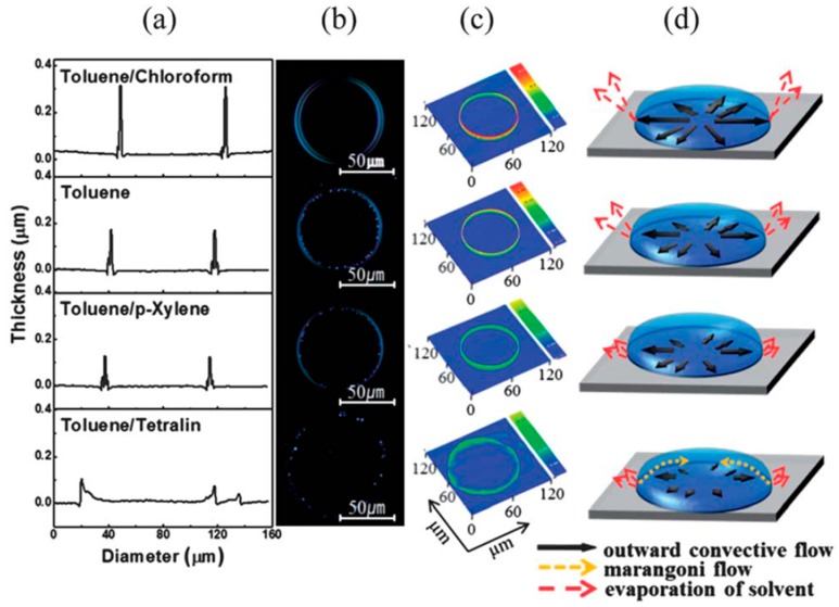
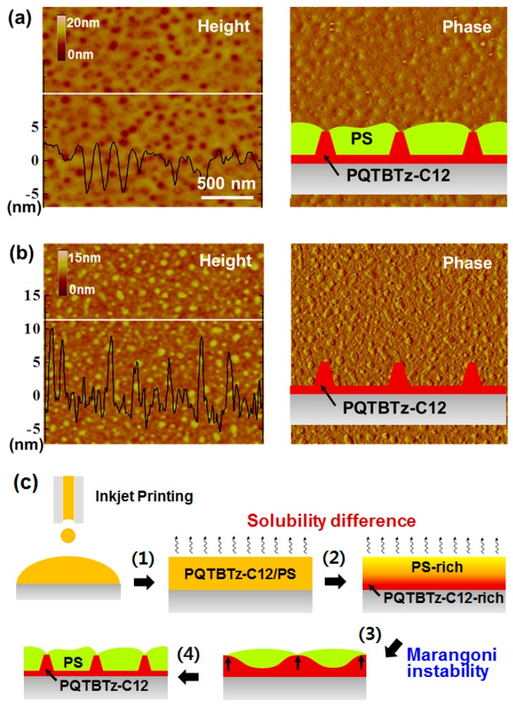
Recent advances in inkjet-printed organic field-effect transistors (OFETs) based on organic semiconductor/insulating polymer blends are reviewed in this article. Organic semiconductor/insulating polymer blends are attractive ink candidates for enhancing the jetting properties, inducing uniform film morphologies, and/or controlling crystallization behaviors of organic semiconductors. Representative studies using soluble acene/insulating polymer blends as an inkjet-printed active layer in OFETs are introduced with special attention paid to the phase separation characteristics of such blended films. In addition, inkjet-printed semiconducting/insulating polymer blends for fabricating high performance printed OFETs are reviewed.

Keywords: inkjet printing; organic field-effect transistor; organic semiconductor; polymer blend; printed electronics; soluble acene.


Conflict of interest statement

The authors declare no conflict of interest.

Figures

Figure 1
Figure 1
Schematic diagram showing the inkjet printing process. The right/top inset shows scanning electron microscopy (SEM) image of inkjet-printed poly(3,4-ethylenedioxythiophene)/poly(styrenesulfonate) (PEDOT/PSS) electrode [5]. Copyright 2013 American Chemical Society.
Figure 2
Figure 2
Droplet profiles of (a) 6,13-Bis(triisopropylsilylethynyl) pentacene (TIPS-pentacene, 1 g/dL in anisole); (b) TIPS-pentacene/polystyrene (PS) blends (1:1 w/w, 1 g/dL in anisole); and (c) PS (0.5 g/dL in anisole. Optical microscopy images of inkjet-printed TIPS-pentacene/PS blend films using (d) anisole solution or (e) anisole/acetophenone (90/10) mixed solution [18]. Copyright 2010 Royal Society of Chemistry.
Figure 3
Figure 3
Polarized optical microscopy images showing transition of TIPS-pentacene/PS blend films with increasing wt % of TIPS-pentacene: (a) Substrate temperature at 70 °C; (b) Substrate temperature at 20 °C. Scale bar: 100 μm [45]. Copyright 2011 Elsevier.
Figure 4
Figure 4
(a) Transfer characteristics in saturation regime (VDS = −10 V) for field-effect transistors (FETs) based on pure TIPS-pentacene (open circles in blue) and TIPS-pentacene/PS blend of 67 wt % TIPS-pentacene (solid circles in red); (b) Average field-effect mobilities as a function of TIPS-pentacene weight ratios in FETs with TIPS-pentacene/PS blend film. 2D topography and corresponding surface potential images were measured with scanning Kelvin probe microscopy (SKPM) of (c) pure TIPS-pentacene film or (d) TIPS-pentacene/PS blend film (67 wt % TIPS-pentacene) [45]. Copyright 2011 Elsevier.
Figure 5
Figure 5
Polarized optical microscopy images of inkjet-printed droplets containing (a); (b) TIPS-pentacene and (c); (d) TIPS-pentacene/PS blend films deposited on (a); (c) pentafluorobenzenethiol (PFBT)-treated Au and (b); (d) trichlorophenylsilane (TCPS)-treated silicon substrates; (eh) Raman intensity of the C–C ring stretch mode as a function of polarization angle taken from red circle points in (ad) [46]. Copyright 2011 American Chemical Society; (i) Polarized optical microscopy images of ink-jet printed TIPS-pentacene/PS blends: on-centered (left) and off-centered (right); (j) Average field-effect mobility of FETs based on on- and off-centered ink-jet printed deposits [47]. Copyright 2013 Elsevier.
Figure 6
Figure 6
(a) Average field-effect mobility (left) of FETs based on inkjet-printed TIPS-pentacene/amorphous polycarbonate (APC) blends (left) and Gibbs free energy of mixing (right) as a function of blending ratio; (b) Average mobility and threshold voltage of FETs based on inkjet-printed TIPS-pentacene/APC blends with respect to solvent mixture [48]. Copyright 2013 Royal Society of Chemistry.
Figure 7
Figure 7
Polarized optical microscopy images of (a) inkjet-printed TIPS-pentacene and (bf) TIPS-pentacene/APC blends (1:1), (1:2), (1:4), (1:6), (1:8), respectively [48]. Copyright 2013 Royal Society of Chemistry.
Figure 8
Figure 8
Mixed solvent approach in TIPS-pentacene/APC blends: (a) Profile images; (b) polarized optical microscopy images; (c) 3D profile images; and (d) schematic drawings of inkjet-printed TIPS-pentacene/APC droplets [48]. Copyright 2013 Royal Society of Chemistry.
Figure 9
Figure 9
(a) Polarized optical microscopy images of TIPS-pentacene deposits on poly(α-methlystyrene) (PαMS) layers of various thicknesses. Top: 59 kDa (1, 30, 60 nm), Bottom: 858 kDa (7, 40, 70 nm). Substrate temperature was kept at 70 °C [49]. Copyright 2010 Wiley; (b) Schematic of printing process of 2,8-difluoro-5,11-bis(triethylsilylethynyl)anthradithiophene (diF-TESADT)/poly(methyl methacrylate) (PMMA) blend using picoliter fluidic dispensing system; (c) Surface profiles of diF-TESADT/PMMA blend before and after selective removal of diF-TESADT [51]. Copyright 2015 Nature Publishing Group.
Figure 10
Figure 10
(a) Chemical structure of poly(didodecylquaterthiophene-alt-didodecylbithiazole) (PQTBTz-C12); Photographic images of solution (left), droplet profile (right) of (b) PQTBTz-C12 and droplet profile of (c) PQTBTz-C12/PS blend. The photographic images on the left were collected at various stages of aging [54]. Copyright 2016 Wiley.
Figure 11
Figure 11
Atomic force microscopy (AFM) height (left) and phase (right) images of (a) inkjet-printed PQTBTz-C12/PS blend film and (b) remaining PQTBTz-C12 film after selective removal of PS. Insets show schematic drawings; (c) Schematic representations showing formation of PQTBTz-C12/PS blend film during drying of inkjet-printed droplets [54]. Copyright 2016 Wiley.
Figure 12
Figure 12
(a) Schematic showing inkjet printing of poly(3-hexylthiophene) (P3HT)/PS blend and formation P3HT nanofibers embedded in PS; Environmental stabilities of FETs based on P3HT (b) and P3HT/PS (20:80) blend (c). Mixed solvent with chlorobenzene (CB) and cyclohexanone (CHN) (80:20) was used to prepare P3HT/PS blend solution [56]. Copyright 2010 Wiley.
Figure 13
Figure 13
(a) Field-effect mobility and Ion/Ioff of P3HT/PS (20:80) FETs as a function of CHN composition in CB/CHN mixed solvent; (b) AFM phase images of inkjet-printed P3HT/PS blend films from CB (left) and CB/CHN (80:20) mixed solvent (right); (c) Ion/Ioff and (d) field-effect mobility/conductivity as a function of P3HT content [56]. Copyright 2010 Wiley.

Similar articles

Cited by

References

    1. Torsi L., Magliulo M., Manoli K., Palazzo G. Organic field-effect transistor sensors: A tutorial review. Chem. Soc. Rev. 2013;42:8612–8628. doi: 10.1039/c3cs60127g. - DOI - PubMed
    1. Sirringhaus H. 25th anniversary article: Organic field-effect transistors: The path beyond amorphous silicon. Adv. Mater. 2014;26:1319–1335. doi: 10.1002/adma.201304346. - DOI - PMC - PubMed
    1. Lee W.H., Choi H.H., Kim D.H., Cho K. 25th anniversary article: Microstructure dependent bias stability of organic transistors. Adv. Mater. 2014;26:1660–1680. doi: 10.1002/adma.201304665. - DOI - PubMed
    1. Sirringhaus H. Reliability of organic field-effect transistors. Adv. Mater. 2009;21:3859–3873. doi: 10.1002/adma.200901136. - DOI
    1. Kang B., Lee W.H., Cho K. Recent advances in organic transistor printing processes. ACS Appl. Mater. Interfaces. 2013;5:2302–2315. doi: 10.1021/am302796z. - DOI - PubMed