. 2017 Aug 15;50(8):1976-1987.
doi: 10.1021/acs.accounts.7b00218. Epub 2017 Aug 4.

Electrospun Nanofibers: New Concepts, Materials, and Applications

Affiliations

Electrospun Nanofibers: New Concepts, Materials, and Applications

Jiajia Xue et al. Acc Chem Res. .

Abstract

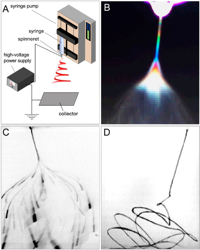
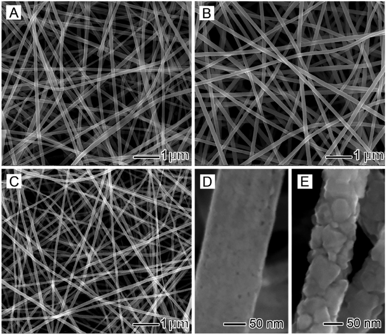
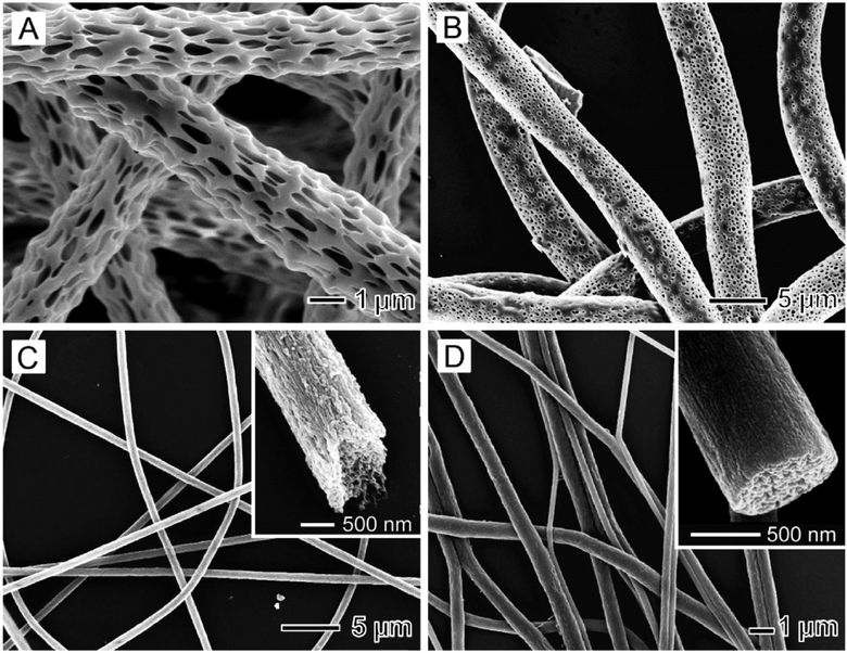
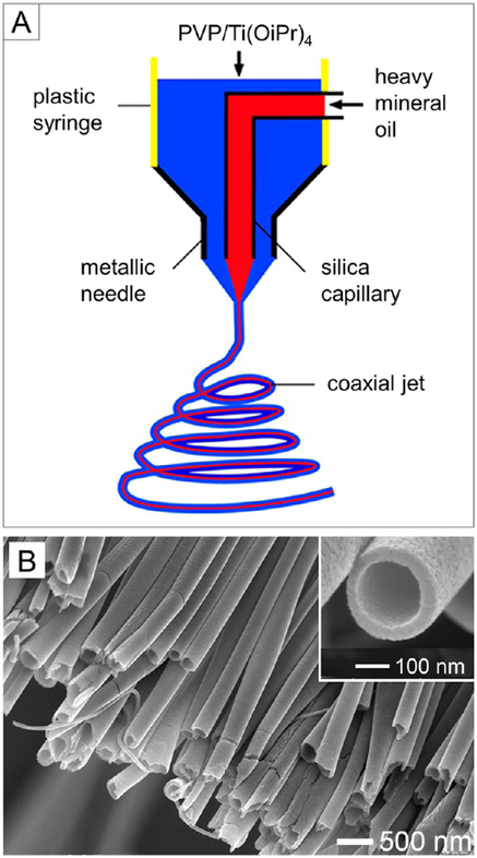
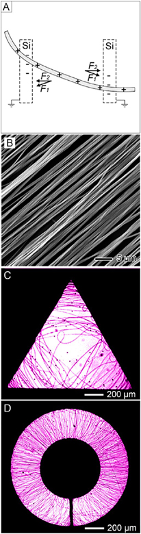
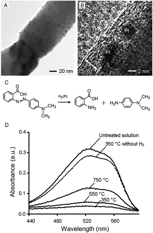
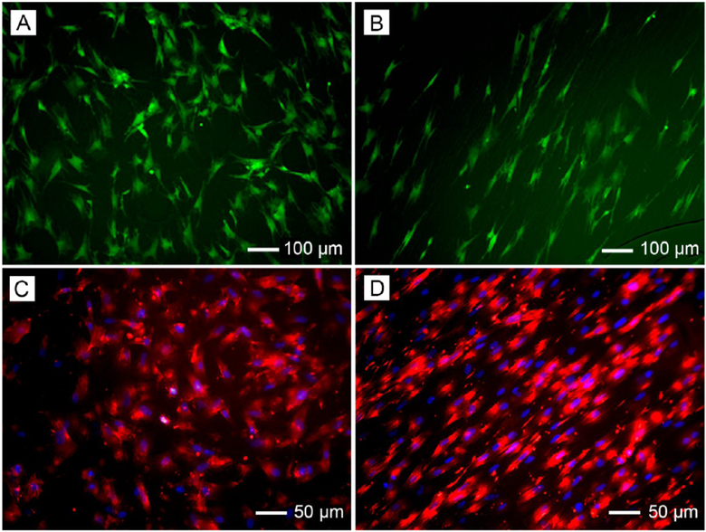
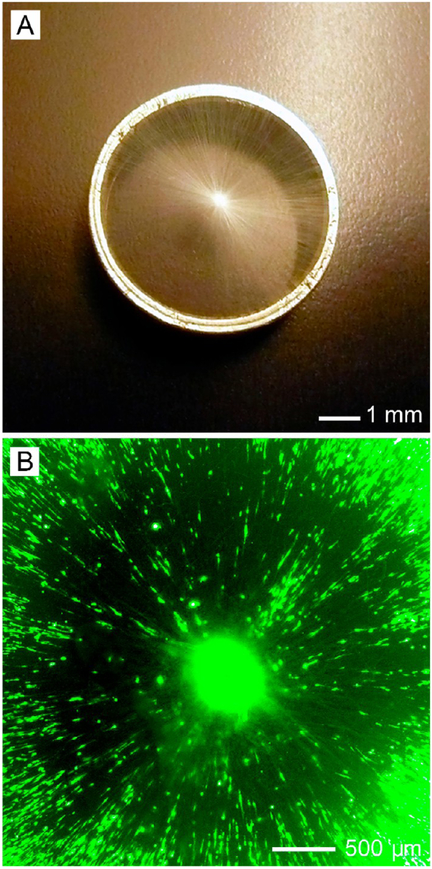
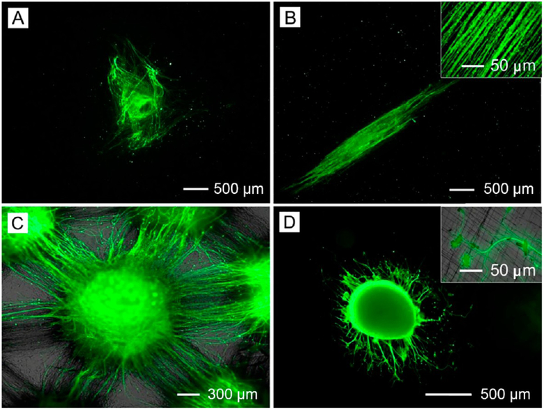
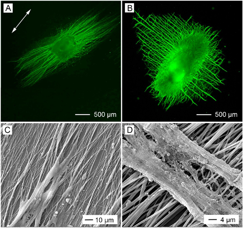
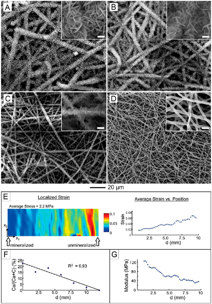
Electrospinning is a simple and versatile technique that relies on the electrostatic repulsion between surface charges to continuously draw nanofibers from a viscoelastic fluid. It has been applied to successfully produce nanofibers, with diameters down to tens of nanometers, from a rich variety of materials, including polymers, ceramics, small molecules, and their combinations. In addition to solid nanofibers with a smooth surface, electrospinning has also been adapted to generate nanofibers with a number of secondary structures, including those characterized by a porous, hollow, or core-sheath structure. The surface and/or interior of such nanofibers can be further functionalized with molecular species or nanoparticles during or after an electrospinning process. In addition, electrospun nanofibers can be assembled into ordered arrays or hierarchical structures by manipulation of their alignment, stacking, and/or folding. All of these attributes make electrospun nanofibers well-suited for a broad spectrum of applications, including those related to air filtration, water purification, heterogeneous catalysis, environmental protection, smart textiles, surface coating, energy harvesting/conversion/storage, encapsulation of bioactive species, drug delivery, tissue engineering, and regenerative medicine. Over the past 15 years, our group has extensively explored the use of electrospun nanofibers for a range of applications. Here we mainly focus on two examples: (i) use of ceramic nanofibers as catalytic supports for noble-metal nanoparticles and (ii) exploration of polymeric nanofibers as scaffolding materials for tissue regeneration. Because of their high porosity, high surface area to volume ratio, well-controlled composition, and good thermal stability, nonwoven membranes made of ceramic nanofibers are terrific supports for catalysts based on noble-metal nanoparticles. We have investigated the use of ceramic nanofibers made of various oxides, including SiO2, TiO2, SnO2, CeO2, and ZrO2, as supports for heterogeneous catalysts based on noble metals such as Au, Pt, Pd, and Rh. On the other hand, the diameter, composition, alignment, porosity, and surface properties of polymeric nanofibers can be engineered in a controllable fashion to mimic the hierarchical architecture of an extracellular matrix and help manipulate cell behaviors for tissue engineering and regenerative medicine. To this end, we can mimic the native structure and morphology of the extracellular matrix in tendon using uniaxially aligned nanofibers; we can use radially aligned nanofibers to direct the migration of cells from the periphery to the center in an effort to speed up wound healing; and we can also use uniaxially aligned nanofibers to guide and expedite the extension of neurites for peripheral nerve repair. Furthermore, we can replicate the anatomic structures at the tendon-to-bone insertion using nanofiber scaffolds with graded mineral coatings. In this Account, we aim to demonstrate the unique capabilities of electrospun nanofibers as porous supports for heterogeneous catalysis and as functional scaffolds for tissue regeneration by concentrating on some of the recent results.


Conflict of interest statement

The authors declare no competing financial interest.

Figures

Figure 1.
Figure 1.
(A) Schematic illustration of a typical setup for electrospinning. Photographs of the jet obtained with (B) a digital video camera using the interference color technique, (C) a standard camera at an exposure time of 33 ms, and (D) a high-speed camera at an exposure time of 0.1 ms. Adapted with permission from (B) ref and (C, D) ref . Copyright 2008 Elsevier and 2005 De Gruyter, respectively.
Figure 2.
Figure 2.
(A) SEM image of composite nanofibers comprising PVP and amorphous TiO2. (B, C) SEM images of ceramic nanofibers made of anatase and rutile, respectively. (D, E) High-magnification views of the nanofibers in (B) and (C), respectively.
Figure 3.
Figure 3.
(A) SEM image of porous PLLA fibers. (B–D) SEM images of porous nanofibers composed of PCL, PAN, and PVDF, respectively, obtained by electrospinning into liquid nitrogen and then drying under vacuum. The insets in (C) and (D) show the ends of broken fibers, revealing the highly porous structure. Adapted with permission from (A) ref and (B–D) ref . Copyright 2008 Wiley-VCH and 2006 American Chemical Society, respectively.
Figure 4.
Figure 4.
(A) Schematic illustration of the spinneret for coaxial electrospinning. (B) SEM image of TiO2 hollow nanofibers. The inset shows an SEM image of the hollow nanofiber at a higher magnification. Adapted from ref . Copyright 2004 American Chemical Society.
Figure 5.
Figure 5.
(A) Schematic illustration of the electrostatic forces applied to a charged nanofiber spanning across an insulating gap. The electrostatic force (F1) originates from the electric field while the Coulomb interactions (F2) arise from the positive charges on the nanofibers and the negative charges on the two grounded electrodes. (B) SEM image of the uniaxially aligned PCL nanofibers. (C, D) Optical micrographs showing gold electrodes (dark area) of different shapes patterned on insulating, quartz substrates. Only those fibers deposited on insulating regions (bright areas) are visible. Adapted from (A, B) ref and (C, D) ref . Copyright 2003 and 2005, respectively, American Chemical Society.
Figure 6.
Figure 6.
(A) TEM and (B) high-resolution TEM images of a Pt/TiO2 (anatase) nanofiber whose surface was coated with a 4–6 nm thick sheath of amorphous SiO2. (C) Hydrogenation of methyl red.(D) UV–vis spectra of a methyl red solution before and after hydrogenation in the presence of the porous-SiO2/Pt/TiO2 nanofibers. The conversions were 87%, 81%, and 61% for the nanofibers obtained by calcination in air for 2 h at 350, 550, and 750 °C, respectively. Adapted with permission from ref . Copyright 2010 Wiley-VCH.
Figure 7.
Figure 7.
Fluorescence micrographs showing (A, B) tendon fibroblasts seeded on random and uniaxially aligned PCL nanofibers and stained with fluorescein diacetate and (C, D) Schwann cells seeded on random and uniaxially aligned PCL nanofibers, with the actin cytoskeleton and nuclei stained with rhodamine phalloidin (red) and 4′,6-diamidino-2-phenylindole (blue), respectively. Adapted with permission from (A, B) ref and (C, D) ref . Copyright 2010 Royal Society of Chemistry and 2014 American Chemical Society, respectively.
Figure 8.
Figure 8.
(A) Photograph of radially aligned nanofibers on a ring collector and (B) fluorescence micrograph of dural fibroblasts on a scaffold of radially aligned nanofibers. Adapted from ref . Copyright 2010 American Chemical Society.
Figure 9.
Figure 9.
Fluorescence micrographs showing the neurite fields extending from DRG cultured on (A) random, (B) uniaxially aligned, (C) microwell-arrayed, and (D) double-layered PCL nanofiber scaffolds. The insets in (B) and (D) show enlarged views of the neurites. The DRG were stained with antineurofilament 200 (green). Adapted with permission from (A, B) ref , (C) ref , and (D) ref . Copyright 2014 American Chemical Society, 2011 Wiley-VCH, and 2009 American Chemical Society, respectively.
Figure 10.
Figure 10.
Fluorescence micrographs showing the neurite fields extending from DRG cultured on (A) laminin-coated nanofibers and (B) nanofibers deposited on PEG-coated coverslips. The arrow in (A) indicates the direction of alignment for the underlying nanofibers in (A) and (B). The DRG were stained with antineurofilament 200 (green). (C, D) SEM images showing both the nanofibers and neurites for the samples displayed in (A) and (B), respectively. Adapted from ref . Copyright 2014 American Chemical Society.
Figure 11.
Figure 11.
SEM images of calcium phosphate coatings on a plasma-treated nonwoven mat of PLGA nanofibers and mechanical testing of the graded scaffolds. The images were taken from different regions, with d corresponding to (A) 0, (B) 6, (C) 9, and (D) 11 mm. The scale bars in the insets are 2 μm. (E) Strain in the x1 direction for specific values of stress. The strain increases with increasing stress and is the highest on the nonmineralized side of the scaffold. (F) Energy-dispersive X-ray analysis of the graded scaffold. There is a linear decrease in calcium phosphate along the length of the scaffold. (G) Young’s modulus of different spots along the gradient. The modulus decreases with decreasing calcium phosphate content. Adapted from ref . Copyright 2009 American Chemical Society.

Similar articles

Cited by

References

    1. Boys CV On the Production, Properties, and Some Suggested Uses of the Finest Threads. Proc. Phys. Soc. London 1887, 9, 8–19.
    1. Cooley JF Apparatus for Electrically Dispersing Fluids. U.S. Patent 692,631, 1902.
    1. Morton WJ Method of Dispersing Fluid. U.S. Patent 705,691, 1902.
    1. Formhals A; Gastell SR Process and Apparatus for Preparing Artificial Threads. U.S. Patent 1,975,504, 1934.
    1. Formhals A Method and Apparatus for Spinning. U.S. Patent 2,349,950, 1944.

Publication types

LinkOut - more resources