. 2018 Mar;36(3):1002-1011.
doi: 10.1002/jor.23673. Epub 2017 Aug 21.

Customized, degradable, functionally graded scaffold for potential treatment of early stage osteonecrosis of the femoral head

Affiliations

Customized, degradable, functionally graded scaffold for potential treatment of early stage osteonecrosis of the femoral head

Toshiyuki Kawai et al. J Orthop Res. 2018 Mar.

Abstract

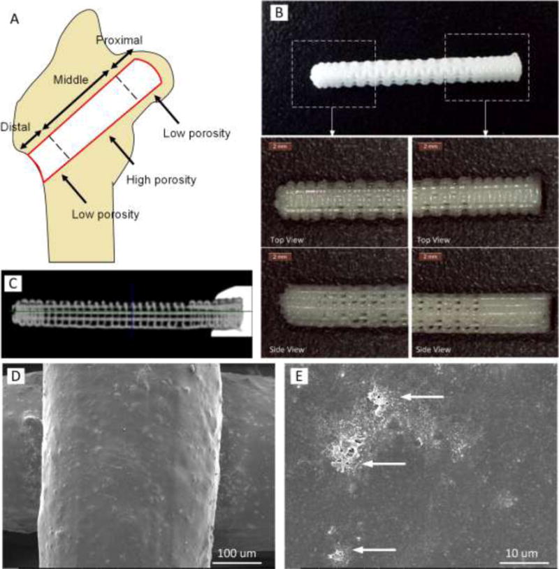
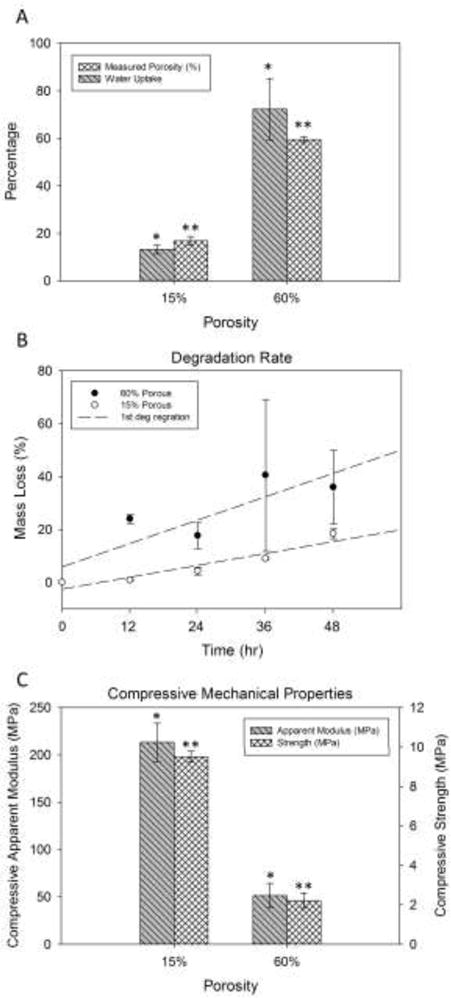
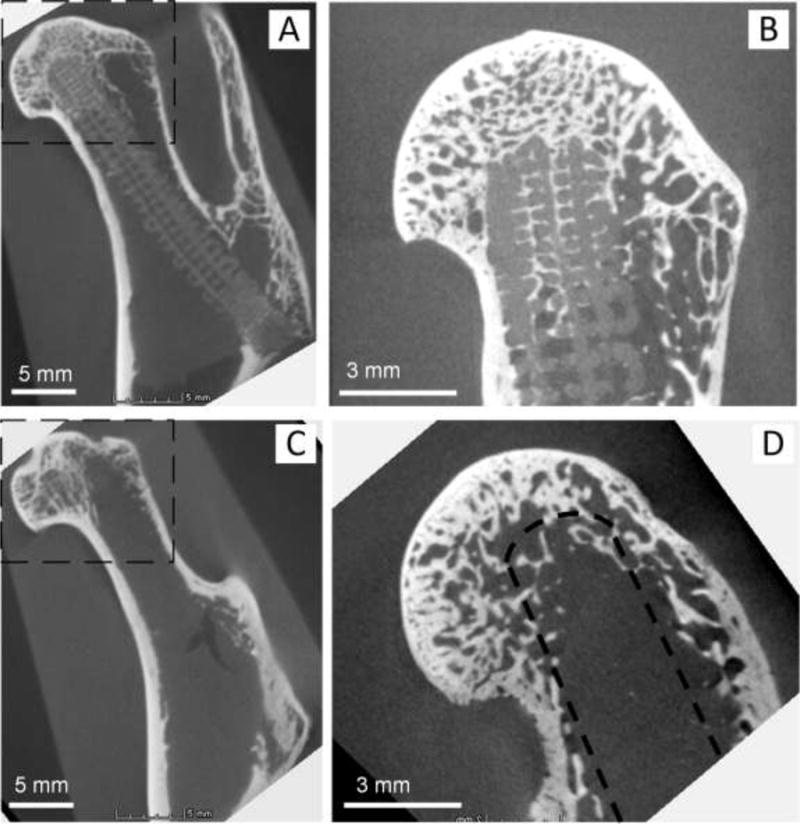
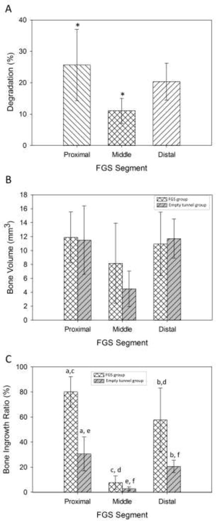
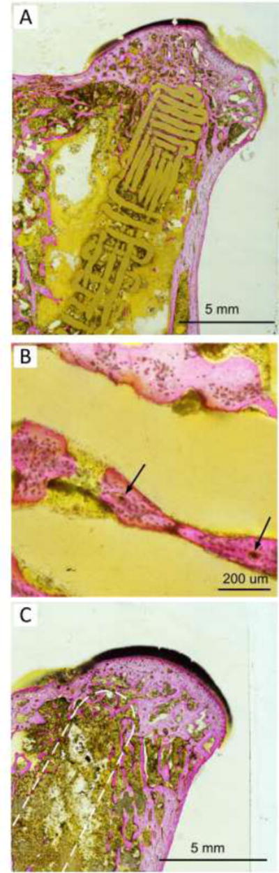
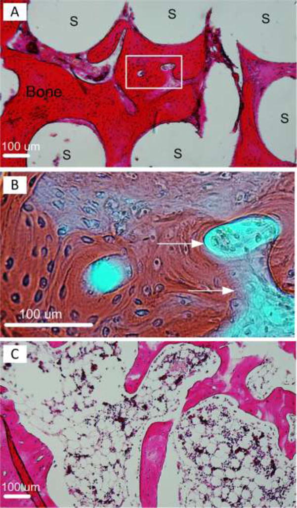
Osteonecrosis of the femoral head (ONFH) is a debilitating disease that results in progressive collapse of the femoral head and subsequent degenerative arthritis. Few treatments provide both sufficient mechanical support and biological cues for regeneration of bone and vascularity when the femoral head is still round and therefore salvageable. We designed and 3D printed a functionally graded scaffold (FGS) made of polycaprolactone (PCL) and β-tricalcium phosphate (β-TCP) with spatially controlled porosity, degradation, and mechanical strength properties to reconstruct necrotic bone tissue in the femoral head. The FGS was designed to have low porosity segments (15% in proximal and distal segments) and a high porosity segment (60% in middle segment) according to the desired mechanical and osteoconductive properties at each specific site after implantation into the femoral head. The FGS was inserted into a bone tunnel drilled in rabbit femoral neck and head, and at 8 weeks after implantation, the tissue formation as well as scaffold degradation was analyzed. Micro-CT analysis demonstrated that the FGS-filled group had a significantly higher bone ingrowth ratio compared to the empty-tunnel group, and the difference was higher at the distal low porosity segments. The in vivo degradation rate of the scaffold was higher in the proximal and distal segments than in the middle segment. Histological analysis of both non-decalcified and calcified samples clearly indicated new bone ingrowth and bone marrow-containing bone formation across the FGS. A 3D printed PCL-β-TCP FGS appears to be a promising customized resorbable load-bearing implant for treatment of early stage ONFH. © 2017 Orthopaedic Research Society. Published by Wiley Periodicals, Inc. J Orthop Res 36:1002-1011, 2018.

Keywords: 3D printing; femoral head; functionally graded scaffold; osteonecrosis; polymer-ceramic composite; resorbable.


Figures

Figure 1
Figure 1
FGS for ONH treatment composed of three segments of spatially-graded porosity: a proximal segment to support the subchondral area, a middle segment located in the main osteonecrotic area of the femoral head, and a distal segment to support the cortical-like structure. (A) A schematic image illustrating how three segments of FGS are located in femoral head. (B) 3D printed PCL-β-TCP of 3.5 mm diameter and 27 mm length with magnified view of distal and proximal segments. (C) Micro CT scan of FGS: low porous (15%) proximal and distal segments as well as high porous (60%) middle region are shown. (D and E) SEM images of scaffold strut surface demonstrating roughness and micro-pores formed after NaOH treatment. Arrows depict clusters of β-TCP on the strut surface.
Figure 2
Figure 2
Physical and mechanical properties of FGS: (A) Porosity and water-uptake of scaffolds for high and low porosity segments of FGS determined via micro CT analysis equal to 16.8 ± 1.8%, 59.5 ± 1.2% and 16.4 ± 1.7% for proximal, middle and distal segment, respectively. Water-uptake yielded values of 15.1 ± 2.1% for dense segments and 72.3 ± 12.9% for the less dense segment, respectively. (B) Accelerated degradation rates of scaffolds of high and low porosity in alkaline medium (5M NaOH) for every 12 h up to 48 h. Both 15% and 60% scaffolds exhibited almost linear degradation rates. (C) Strength and apparent modulus of elasticity of PCL-β-TCP scaffolds with low and high porosity under uniaxial compression.
Figure 3
Figure 3
Representative micro CT images of explants with (A and B) and without FGS (C and D): (B) and (D) are images scanned, focusing on the box area shown in (A) and (C). (A) Micro CT of femoral head with FGS. Lattice pattern and structural integrity of the scaffold were well maintained at 8 weeks after implantation. (B) Mineralized tissue shown in the interconnected macro-pores of proximal FGS in femoral head. (C) Micro CT image of femoral head with empty tunnel. (D) In the empty-tunnel group, most of the space in the bone tunnel remained empty, but there was some mineralized tissue around the tip of the tunnel. A drilled tunnel is depicted by a dashed line.
Figure 4
Figure 4
In vivo evaluation of FGS degradation and new bone formation: (A) Degradation rate of the FGS quantified using CT scans. The degradation rates of the proximal, middle and distal segments were measured 25.7±11.3 %, 11.1±4.0 %, and 20.4±6.9 %, respectively. Groups with star signs are significantly different from each other with p<0.05. (B) The volumes of newly formed bone measured at 8 weeks post-surgery were measured 11.9±3.6 mm3 in the proximal segment, 8.2±5.8 mm3 in the middle segment, 10.9±4.6 mm3 in the distal segment for the scaffold group. (C) Bone ingrowth ratio for the scaffold group was 80.1 ± 12.1 % for the proximal segment, 7.7±5.2 % for the middle segment and 57.7±25.4 % for the distal segment. Groups that are indicated with the same lowercase letters (for example the pairs with letter “a”) are significantly different from each other with p<0.05 as analyzed by a t-test.
Figure 5
Figure 5
This figure demonstrates non-decalcified sections of osseous ingrowth in decompression tunnel in the presence and absence of FGS with Stevenel blue and Van Gieson’s picro fuchsin staining after 8 weeks of implantation. (A) demonstrates non-decalcified sections of osseous ingrowth within the pores of FGS. (B) shows newly formed bone tissue in the porous area and in direct contact with the lattice strut at a higher magnification. Blood vessels containing osteon-like structures within the newly formed bone tissues were depicted by arrows. (C) shows bone ingrowth in the tip area of the empty tunnel samples. The position of the drilled tunnel is depicted by a dashed line.
Figure 6
Figure 6
Decalcified sections of newly formed bone within FGS pores with H&E staining. (A) Extensive new bone formation with bone marrow shown in red. White area labeled “S” are FGS struts. (B) shows a magnified image of the area depicted by dashed lined in (A). Blood vessels containing osteon-like structures were depicted by arrows. (C) shows bone marrow formation in the newly formed bone.

References

    1. Amanatullah DF, Strauss EJ, PE DC. Current management options for osteonecrosis of the femoral head: part II, operative management. Am J Orthop (Belle Mead NJ) 2011;40:216–225. - PubMed
    1. Waewsawangwong W, Ruchiwit P, Huddleston JI, et al. Hip arthroplasty for treatment of advanced osteonecrosis: comprehensive review of implant options, outcomes and complications. Orthop Res Rev. 2012;2016:8, 13–29. - PMC - PubMed
    1. Stevens K, Tao C, Lee SU, et al. Subchondral fractures in osteonecrosis of the femoral head: comparison of radiography, CT, and MR imaging. AJR Am J Roentgenol. 2003;180:363–368. - PubMed
    1. Pritchett JW. Statin therapy decreases the risk of osteonecrosis in patients receiving steroids. Clin Orthop Relat Res. 2001:173–178. - PubMed
    1. Wang GJ, Cui Q, Balian G. The Nicolas Andry award. The pathogenesis and prevention of steroid-induced osteonecrosis. Clin Orthop Relat Res. 2000:295–310. - PubMed

Publication types

LinkOut - more resources