. 2014 Jun 25;7(7):4963-4981.
doi: 10.3390/ma7074963.

Experimental Investigation of the Effect of the Driving Voltage of an Electroadhesion Actuator

Affiliations

Experimental Investigation of the Effect of the Driving Voltage of an Electroadhesion Actuator

Keng Huat Koh et al. Materials (Basel). .

Abstract

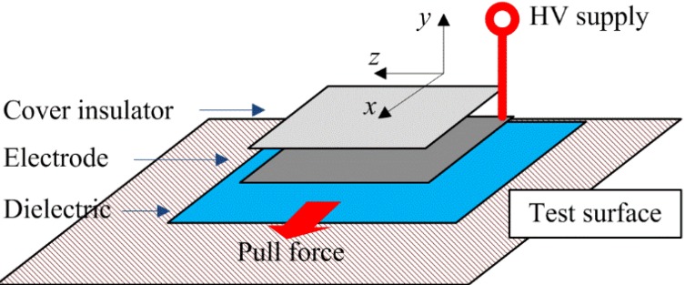
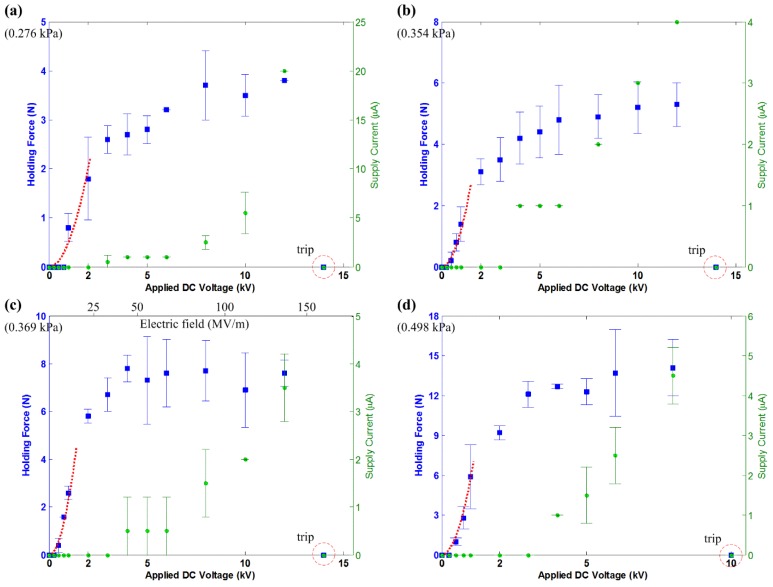
This paper investigates the effect of driving voltage on the attachment force of an electroadhesion actuator, as the existing literature on the saturation of the adhesive force at a higher electric field is incomplete. A new type of electroadhesion actuator using normally available materials, such as aluminum foil, PVC tape and a silicone rubber sheet used for keyboard protection, has been developed with a simple layered structure that is capable of developing adhesive force consistently. The developed actuator is subjected to the experiment for the evaluation of various test surfaces; aluminum, brick, ceramic, concrete and glass. The driving high voltage is varied in steps to determine the characteristics of the output holding force. Results show a quadratic relation between F (adhesion force) and V (driving voltage) within the 2 kV range. After this range, the F-V responses consistently show a saturation trend at high electric fields. Next, the concept of the leakage current that can occur in the dielectric material and the corona discharge through air has been introduced. Results show that the voltage level, which corresponds to the beginning of the supply current, matches well with the beginning of the force saturation. With the confirmation of this hypothesis, a working model for electroadhesion actuation is proposed. Based on the experimental results, it is proposed that such a kind of actuator can be driven within a range of optimum high voltage to remain electrically efficient. This practice is recommended for the future design, development and characterization of electroadhesion actuators for robotic applications.

Keywords: corona discharge; dielectric actuation; electroadhesion actuator; electrostatic force; holding force; leakage current.


Conflict of interest statement

The authors declare no conflict of interest.

Figures

Figure 1
Figure 1
Parallel plate capacitor shown with a linear dielectric partially inserted. Note that the x-y-z axes shown here are an essential convention followed throughout this paper. From here, the x and z directions are considered parallel to the system, while the y direction is defined as perpendicular to the system.
Figure 2
Figure 2
Schematic of the electroadhesion actuator showing an exploded view of the component layers. The direction of the pull force is also shown. HV, high voltage.
Figure 3
Figure 3
Photograph of the electroadhesion actuators. Naming convention: A7×4, the actuator with material Combination A with an electrode dimension of 7 inches in length and 4 inches in width.
Figure 4
Figure 4
Applying HV to the electroadhesion actuator while placing it on the test surface. (a) The induced charge as a result of polarization in dielectric Material 1; (b) the electrical schematic and the E field model.
Figure 5
Figure 5
Free body diagrams of the actuator applied to an inclined vertical surface. (a) The applied shear force is per the experimental setup (+x direction), resulting in FV,x and Ffriction opposing this external force; (b) if the shear force is applied in the opposite direction, then FV,x and Ffriction will result in an opposite direction; (c) a rather small peel force at a small angle β will detach the actuator from the surface easily.
Figure 6
Figure 6
The experimental setup for shear force measurement (a supplemental video for the experiment is available).
Figure 7
Figure 7
The measured holding force and supply current for the electroadhesion actuator on the aluminum surface, shown with the tripped voltage level. The dashed line describes Equation (2) with the following parameters: εr = 3.9, A = 18.06 × 10⁻³ m2, d = 200 µm. The solid line describes Equation (12) with µs = 2.36.
Figure 8
Figure 8
The measured holding force and supply current for electroadhesion actuators on the brick surface, shown with the tripped voltage level. The dashed line describes a quadratic fit over the data, which follows Equation (13). (a) B7×4, c = 0.12; (b) B7×5, c = 1.0; (c) B7×6, c = 2.3; (d) B7×8, c = 2.0.
Figure 9
Figure 9
The measured holding force and supply current for the electroadhesion actuators on ceramic tiles, shown with the tripped voltage level. The dashed line describes a quadratic fit over the data, which follows Equation (13). (a) B7×4, c = 3.4; (b) B7×5, c = 7.5; (c) B7×6, c = 12; (d) B7×8, c = 13.
Figure 10
Figure 10
The measured holding force and supply current for the electroadhesion actuators on the concrete slab, shown with the tripped voltage level. The dashed line describes a quadratic fit over the data, which follows Equation (13). (a) B7×4, c = 0.5; (b) B7×5, c = 1.2; (c) B7×6, c = 2.3; (d) B7×8, c = 5.8.
Figure 11
Figure 11
The measured holding force and supply current for the electroadhesion actuators on the glass panel, shown with the tripped voltage level. The dashed line describes a quadratic fit over the data, which follows Equation (13). (a) B7×4, c = 1.8; (b) B7×5, c = 18; (c) B7×6, c = 2.8.; (d) B7×8, c = 2.0. (The experiment on glass panel is shown in the supplementary video).
Figure 12
Figure 12
The working model for the electroadhesion actuator depicting (a) the second order characteristics and (b) the third order characteristics.

References

    1. Monkman G.J. An analysis of astrictive prehension. Int. J. Rob. Res. 1997;16:1–10. doi: 10.1177/027836499701600101. - DOI
    1. Chen X.Q., Sarhadi M. Investigation of electrostatic force for robotic lay-up of composite fabrics. Mechatronics. 1992;2:363–373. doi: 10.1016/0957-4158(92)90003-7. - DOI
    1. Monkman G.J. Robot grippers for use with fibrous materials. Int. J. Rob. Res. 1995;14:144–151. doi: 10.1177/027836499501400204. - DOI
    1. Zhang Z. Modeling and analysis of electrostatic force for robot handling of fabric materials. IEEE/ASME Trans. Mechatron. 1999;4:39–49. doi: 10.1109/3516.752083. - DOI
    1. Yatsuzuka K., Hatakeyama F., Asano K., Aonuma S. Fundamental characteristics of electrostatic wafer chuck with insulating sealant. IEEE Trans. Ind. Appl. 2000;36:510–516. doi: 10.1109/28.833768. - DOI