. 2017 Aug 8;7(1):7545.
doi: 10.1038/s41598-017-06144-9.

Single Microfluidic Electrochemical Sensor System for Simultaneous Multi-Pulmonary Hypertension Biomarker Analyses

Affiliations

Single Microfluidic Electrochemical Sensor System for Simultaneous Multi-Pulmonary Hypertension Biomarker Analyses

GeonHui Lee et al. Sci Rep. .

Abstract

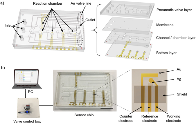
Miniaturized microfluidic biosensors have recently been advanced for portable point-of-care diagnostics by integrating lab-on-a-chip technology and electrochemical analysis. However, the design of a small, integrated, and reliable biosensor for multiple and simultaneous electrochemical analyses in a single device remains a challenge. Here, we present a simultaneous microfluidic electrochemical biosensing system to detect multiple biomarkers of pulmonary hypertension diseases in a single device. The miniaturized biosensor, which is composed of five chambers, is precisely and individually controlled using in-house-built pneumatic microvalves to manipulate the flow pathway. Each chamber is connected to an electrochemical sensor designed to detect four different biomarkers plus a reference control. Our design allows for loading of multiple reagents for simultaneous analyses. On the basis of the developed microfluidic electrochemical sensor system, we successfully detected four well-defined pulmonary hypertension-associated biomarkers, namely, fibrinogen, adiponectin, low-density lipoprotein, and 8-isoprostane. This novel approach offers a new platform for a rapid, miniaturized, and sensitive diagnostic sensor in a single device for various human diseases.


Conflict of interest statement

The authors declare that they have no competing interests.

Figures

Figure 1
Figure 1
Schematic illustration of the microfluidic system for electrochemical analysis in a single device. (a) Schematic description of the microfluidic system integrated electrochemical sensor. The microfluidic electrochemical biosensor is composed of a glass bottom layer with electrodes, PDMS channel/chamber layer, PDMS membrane, and PDMS pneumatic valve layer. (b) Schematic diagram of the experimental setup of the microfluidic electrochemical sensor system. The microfluidic electrochemical biosensor is connected to a PC and a control box to enhance transportability (scale bar is 2 cm).
Figure 2
Figure 2
Principle of the on/off pneumatic microvalve. Schematic description of the (a) microfluidic electrochemical biosensor with a control box for the pneumatic microvalve, (b) valve-on status, (c) side view, (d) valve-off status, and (e) side view.
Figure 3
Figure 3
Schematic illustration and photographs of the individual flow control. (ae) The arrows indicate the flow pathway in (left) the microfluidic electrochemical biosensor and (right) the distilled water with ink showing the valve performance. Five samples were loaded and filled in each microchamber. This process illustrates the preparation of the immunoaffinity layers. (f) Main fluid flow passing through each chamber. This process illustrates that the target material could react in each microchamber.
Figure 4
Figure 4
Electrochemical characterization of the microfluidic sensor system. (a) CV scans for each of the five electrodes. The scan rate is 50 mV/s. (b) SWV scans for each of the five electrodes. (c) CV scans of an electrode at 25, 50, 100, 150, 200, 300 mV/s scan rates. (d) Influence of the square root of the scan rate on the (black) cathodic and (red) anodic peak currents. The electrolyte is 5 mM K3Fe(CN)6 + 0.1 M KCl in 10 mM PBS.
Figure 5
Figure 5
SWV measurements of the current (black solid line) before and after binding of the specific biomarker at (blue solid line) 1 ng/mL and (red solid line) 1 µg/mL concentration. The signal represents the case of (a) Chamber 1: reference signal, (b) Chamber 2: 8-isoprostane, (c) Chamber 3: adiponectin, (d) Chamber 4: fibrinogen, and (e) Chamber 5: LDL. The electrolyte is 5 mM K3Fe(CN)6 + 0.1 M KCl in 10 mM PBS.

References

    1. Saliterman, S. Fundamentals of BioMEMS and medical microdevices Vol. 153 (SPIE press, 2006).
    1. Ali MA, et al. Nanostructured anatase-titanium dioxide based platform for application to microfluidics cholesterol biosensor. Applied Physics Letters. 2012;101:084105. doi: 10.1063/1.4747714. - DOI
    1. Lin C-C, Wang J-H, Wu H-W, Lee G-B. Microfluidic immunoassays. Journal of the Association for Laboratory Automation. 2010;15:253–274. doi: 10.1016/j.jala.2010.01.013. - DOI
    1. Linder V. Microfluidics at the crossroad with point-of-care diagnostics. Analyst. 2007;132:1186–1192. doi: 10.1039/b706347d. - DOI - PubMed
    1. Rackus DG, Shamsi MH, Wheeler AR. Electrochemistry, biosensors and microfluidics: a convergence of fields. Chemical Society Reviews. 2015;44:5320–5340. doi: 10.1039/C4CS00369A. - DOI - PubMed

Publication types

MeSH terms