Review
. 2015 Oct 9;8(10):6806-6848.
doi: 10.3390/ma8105343.

Polymer/Carbon-Based Hybrid Aerogels: Preparation, Properties and Applications

Affiliations
Review

Polymer/Carbon-Based Hybrid Aerogels: Preparation, Properties and Applications

Lizeng Zuo et al. Materials (Basel). .

Abstract

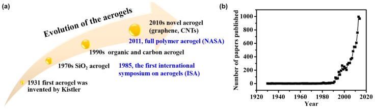
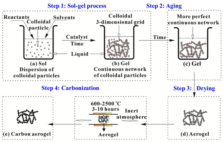
Aerogels are synthetic porous materials derived from sol-gel materials in which the liquid component has been replaced with gas to leave intact solid nanostructures without pore collapse. Recently, aerogels based on natural or synthetic polymers, called polymer or organic aerogels, have been widely explored due to their porous structures and unique properties, such as high specific surface area, low density, low thermal conductivity and dielectric constant. This paper gives a comprehensive review about the most recent progresses in preparation, structures and properties of polymer and their derived carbon-based aerogels, as well as their potential applications in various fields including energy storage, adsorption, thermal insulation and flame retardancy. To facilitate further research and development, the technical challenges are discussed, and several future research directions are also suggested in this review.

Keywords: carbon aerogels; hybrids; polymer aerogels; porous; three-dimensional network.


Conflict of interest statement

The authors declare no conflict of interest.

Figures

Figure 1
Figure 1
(a) Evolution of the aerogels. (b) The number of papers published every year during the last decades (search by aerogel from Web of Science).
Figure 2
Figure 2
General preparation process of polymer or carbon aerogels.
Figure 3
Figure 3
SEM images of 1% cellulose aerogel by (a) regular freeze drying; (b) solvent exchange drying; and (c) rapid freeze drying. Reproduced with permission of Ref. [90] (Copyright Elsevier 2004).
Figure 4
Figure 4
Design, processing and cellular architectures of FIBER nanofibrous aerogels. (a) Schematic showing the synthetic steps. (1) Flexible PAN/BA-a and SiO2 nanofiber membranes are produced by electrospinning. (2) Homogeneous nanofiber dispersions are fabricated via high-speed homogenization. (3) Uncrosslinked nanofibrous aerogels (NFAs) are prepared by freeze drying nanofiber dispersions. (4) The resultant FIBER NFAs are prepared by the crosslinking treatment. (b) An optical photograph of FIBER NFAs with diverse shapes. (ce) Microscopic architecture of FIBER NFAs at various magnifications, showing the hierarchical cellular fibrous structure. Reproduced with permission of Ref. [113] (Copyright Nature Publishing Group 2014).
Figure 5
Figure 5
(a) Octa(aminophenyl)-silsesquioxane (OAPS) cross-linked polyimide aerogels; (b) polyimide aerogels cross-linked with 1,3,5-triaminophenoxybenzene (TAB) fabricated as flexible thin films or molded to a net shape; and (c) demonstrating strength of the aerogel by supporting the weight of a car. Reproduced with permission of Ref. [99] (Copyright American Chemical Society 2012).
Figure 6
Figure 6
SEM images of PI aerogels synthesized from (a) ODA/BPDA; (b) PPDA/BPDA; (c) DMBZ/BPDA; (d) ODA/BTDA; (e) DMBZ/BTDA; and (f) PPDA/BTDA. Reproduced with permission of Ref. [99] (Copyright American Chemical Society 2012).
Figure 7
Figure 7
Carbon aerogels derived from different biomass: (a) Winter melon, reproduced with permission of Ref. [156] (Copyright American Chemical Society 2014). (b) Watermelon, reproduced with permission of Ref. [158] (Copyright American Chemical Society 2013). (c) Bagasse, reproduced with permission of Ref. [159] (Copyright The Royal Society of Chemistry 2014). (d) Waste paper, reproduced with permission of Ref. [160] (Copyright Wiley-VCH Verlag GmbH & Co. 2014).
Figure 8
Figure 8
(a) Photograph of an aqueous GO dispersion (2 mg·mL−1) before and after hydrothermal reduction at 180 °C for 12 h; (b) photographs of a strong rGO hydrogel allowing easy handling and supporting weight; and (c,d) SEM images of the rGO hydrogel showing interior microstructures. Reproduced with permission of Ref. [50]; (Copyright 2010 American Chemical Society.) (e) SEM images of the surface of graphene aerogel fibers and (f) folded/stretched graphene aerogel fibers; (g,h) SEM images of fracture morphology of graphene aerogel fibers. The arrows indicate the alignment direction of graphene sheets. Macroscopic and microscopic structures of UFAs. Reproduced with permission of Ref. [177] (Copyright American Chemical Society 2012). (i) Digital photograph of UFAs with diverse shapes; (j) A 100 cm3 UFA cylinder standing on a flower like dog’s tail; (k,l) Microscopically porous architecture of a UFA at different magnifications, showing CNT-coated graphene cell walls. Reproduced with permission of Ref. [155] (Copyright Wiley-VCH Verlag GmbH & Co. 2013).
Figure 9
Figure 9
(a) Digital photographs of carbon cryogel (CC), graphene/carbon cryogel (GCC), and Ni-doped graphene/carbon cryogel (NGCC) with the same weight (90 mg) after loading with 200 g weight; (inset) 140 mg Ni-doped graphene/carbon cryogel monolith enduring a weight of 500 g. (b,c) SEM images and (d,e) TEM images of Ni-doped graphene/carbon cryogel. Reproduced with permission of Ref. [179] (Copyright American Chemical Society 2013).
Figure 10
Figure 10
(a) Fabrication process for the 3D Fe3O4/N-doped graphene aerogel catalyst. (bd) SEM images of Fe3O4/N-doped graphene aerogel revealing the 3D macroporous structure and uniform distribution of Fe3O4 nanoparticles in the graphene aerogels. Reproduced with permission of Ref. [62] (Copyright American Chemical Society 2012).
Figure 11
Figure 11
(a) SEM images and (b) galvanostatic charge–discharge curves of graphene/carbon aerogels prepared from carbonization of graphene crosslinked PI aerogels. Reproduced with permission of Ref. [185] (Copyright The Royal Society of Chemistry 2015).
Figure 12
Figure 12
(a) Photographs showing the sorption process of heptane by using a TCF aerogel taken at intervals of 10 s. Heptane stained with Sudan red 5B floating on water was completely absorbed within 40 s. (b) Photographs showing the sorption process of chloroform by using a TCF aerogel. Chloroform stained with Sudan red 5B at the bottom of water was completely absorbed within 5 s. Reproduced with permission of Ref. [186] (Copyright Wiley-VCH Verlag GmbH & Co. 2014).
Figure 13
Figure 13
(a) The adsorption capacities of the MWNT-carbon hybrid aerogels for a selection of several common solvents. (b) Cyclic performance of the thermally treated MWNT-carbon hybrid aerogels for oil adsorption in five cycles. Reproduced with permission of Ref. [202] (Copyright The Royal Society of Chemistry 2013).
Figure 14
Figure 14
(a) Vertical burning test of a nanocomposite foam containing 77% CNF, 10% GO, 10% SEP and 3% BA (in wt %). The panel shows the foam before the test, after 11 s of application of a methane flame, and the foam after the test, showing high fire retardancy. (b) Photographs of CNF and CNF-GO-BA-SEP nanocomposite foams during the cone calorimetry test together with the corresponding peak of heat release rates (pkHRR). The test reveals high combustion resistance for the nanocomposite foam at the limit of non-ignitability, while CNF foams are entirely combusted. Reproduced with permission of Ref. [35] (Copyright Nature Publishing Group 2014).
Figure 15
Figure 15
(a) Photographs of the 1st firing cycle test of the carbon foams (absorb 500 wt % of ethanol and burn in air): (Left) a burning ethanol-wetted foam and (Right) foams after the 1st firing cycle test. (b) Plot of the carbon foam mass vs. the firing cycle. (c) Photographs illustrating the fire-retardancy of a carbonaceous foam by repeatedly firing the sample using a butane/propane gas burner. Reproduced with permission of Ref. [217] (Copyright the Royal Society of Chemistry 2015).

Similar articles

Cited by

References

    1. Du A., Zhou B., Zhang Z.H., Shen J. A special material or a new state of matter: A review and reconsideration of the aerogel. Materials. 2013;6:941–968. doi: 10.3390/ma6030941. - DOI - PMC - PubMed
    1. Burger T., Fricke J. Aerogels: Production, modification and applications. Phys. Chem. Chem. Phys. 1998;102:1523–1528. doi: 10.1002/bbpc.19981021102. - DOI
    1. Fricke J., Emmerling A. Aerogels—Preparation, properties, applications. Struct. Bond. 1992;77:37–87.
    1. Pierre A.C., Pajonk G.M. Chemistry of aerogels and their applications. Chem. Rev. 2002;102:4243–4265. doi: 10.1021/cr0101306. - DOI - PubMed
    1. Cuce E., Cuce P.M., Wood C.J., Riffat S.B. Toward aerogel based thermal superinsulation in buildings: A comprehensive review. Renew. Sust. Energy Rev. 2014;34:273–299. doi: 10.1016/j.rser.2014.03.017. - DOI