. 2017 Aug 21;7(1):8386.
doi: 10.1038/s41598-017-08120-9.

Neuroprosthetic-enabled control of graded arm muscle contraction in a paralyzed human

Affiliations

Neuroprosthetic-enabled control of graded arm muscle contraction in a paralyzed human

David A Friedenberg et al. Sci Rep. .

Abstract

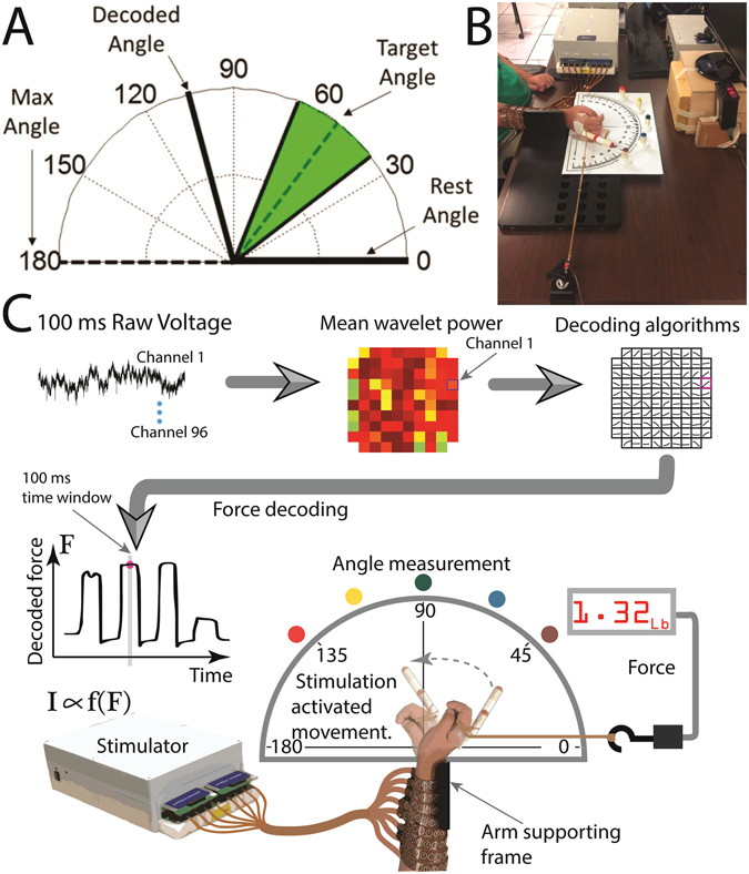
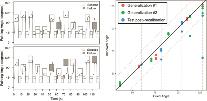
Neuroprosthetics that combine a brain computer interface (BCI) with functional electrical stimulation (FES) can restore voluntary control of a patients' own paralyzed limbs. To date, human studies have demonstrated an "all-or-none" type of control for a fixed number of pre-determined states, like hand-open and hand-closed. To be practical for everyday use, a BCI-FES system should enable smooth control of limb movements through a continuum of states and generate situationally appropriate, graded muscle contractions. Crucially, this functionality will allow users of BCI-FES neuroprosthetics to manipulate objects of different sizes and weights without dropping or crushing them. In this study, we present the first evidence that using a BCI-FES system, a human with tetraplegia can regain volitional, graded control of muscle contraction in his paralyzed limb. In addition, we show the critical ability of the system to generalize beyond training states and accurately generate wrist flexion states that are intermediate to training levels. These innovations provide the groundwork for enabling enhanced and more natural fine motor control of paralyzed limbs by BCI-FES neuroprosthetics.


Conflict of interest statement

The authors declare that they have no competing interests.

Figures

Figure 1
Figure 1
Decoding graded muscle contraction from intracortical activity to control participant’s wrist movement using FES. (A) An example screen used for the virtual graded muscle contraction experiment. Potential angles that can be cued range from 0° to 180°. A target angle is cued with a 15° window on either side of the angle (green) and the thick black line tracks the angle decoded from the participant’s modulation in real-time. (B) Photograph of the graded control of muscle contraction experiment using the BCI-FES system. (C) Flow chart detailing the graded control of muscle contraction experiment where intracortically recorded voltage data are converted to MWP features which are then fed into a decoding algorithm which outputs decoded force, F. The decoded force is then translated into a set of stimulation parameters, I, and the resulting wrist flexion movement is recorded by the load cell and an overhead camera.
Figure 2
Figure 2
Imagined graded muscle contractions modulates neural activity in M1. The top row shows the angle cue that was presented visually to the participant. Each column corresponds to the cue from the top row. The second row shows the mean MWP superimposed on the layout of the MEA. The MWP is averaged over each trial from 0.5 s after cue presentation to 2.5 s after cue presentation. The third row shows the temporal evolution of MWP for each of the 21 trials (for the rest cues we show the first 21 trials) for Channel 24 from 0.5 s before the cue until 2.5 s after the cue. The dashed line at 0 s represents the time of cue presentation. Channel 24 shows a pattern of low MWP for the rest angle, high MWP activity at the lower non-zero angles and decreasing MWP activity as the angles increase. The last row follows the same format as above but represents Channel 67, which shows increasing MWP activity with increased angles.
Figure 3
Figure 3
Neural modulation patterns with imagined graded muscle contractions. (A) The p-values from the beta regression are overlaid over the physical layout of the microelectrode array (MEA). Selected individual channels (highlighted in A) demonstrate a range of neural modulation trends in response to the cued angles. (B) Each column shows selected individual channels where the average MWP (1) increased with increasing cue angles (green), (2) decreased with increasing non-zero cue angles (purple), (3) showed a non-linear relationship with cue angle (blue) and (4) did not show significant response to the cue angles (pink). The average MWP values are calculated the same as in Fig. 2.
Figure 4
Figure 4
The participant generated graded muscle contractions to pull against resistance and point at various target angles. The top figure shows the cued angle (rectangles) and the angle at which the participant was pointing (solid black line) for the first training block. If the participant was successful for a given cue (within 15° of the cue for 2 s continuously), the rectangle is clear; if he failed the cue, it is shaded gray. The bottom figure shows the force measurement in pounds as measured by the load cell aligned in time for the same block. The force exerted closely tracks the wrist flexion as measured by the pointing angle (correlation coefficient 0.933 ± 0.006).
Figure 5
Figure 5
(Left) Participant generates force to match angles that were not used during training in Generalization Blocks 1 (top left) and 2 (bottom left). For these two blocks, the three middle angles were moved to positions the participant had never attempted before. The participant was successful on 22 of 24 cues for the first generalization block and 21 of 24 for generalization block 2. In both blocks, he was successful on 7 of the 9 cues for new angles. (Right) For each cue in the generalization blocks as well as Test Block 4 (post-recalibration) the 2 s where the average achieved angle was closest to the cued angles was extracted and the average achieved angle over that 2 s is plotted against the cued angle. The colors denote the different blocks. The diagonal black line indicates the line of perfect performance where the achieved angle is exactly the cued angle; the upper and lower dotted black lines show the 15° tolerance bands around the middle line. The vertical dashed lines indicate angles used for the Training and Test Blocks 1-4. The plot demonstrates that the participant was not only in the tolerance window during the generalization blocks but also could point to the new angles with similar precision to the angles used during training.

References

    1. Bensmaia SJ, Miller LE. Restoring sensorimotor function through intracortical interfaces: progress and looming challenges. Nature Reviews Neuroscience. 2014;15:313. doi: 10.1038/nrn3724. - DOI - PubMed
    1. Gilja V, et al. Challenges and Opportunities for Next-Generation Intracortically Based Neural Prostheses. Ieee Transactions on Biomedical Engineering. 2011;58:1891. doi: 10.1109/TBME.2011.2107553. - DOI - PMC - PubMed
    1. Kao JC, Stavisky SD, Sussillo D, Nuyujukian P, Shenoy KV. Information Systems Opportunities in Brain-Machine Interface Decoders. Proceedings of the Ieee. 2014;102:666. doi: 10.1109/JPROC.2014.2307357. - DOI
    1. Lebedev MA, Nicolelis MA. Brain–machine interfaces: past, present and future. TRENDS in Neurosciences. 2006;29:536. doi: 10.1016/j.tins.2006.07.004. - DOI - PubMed
    1. Ethier C, Oby ER, Bauman MJ, Miller LE. Restoration of grasp following paralysis through brain-controlled stimulation of muscles. Nature. 2012;485:368. doi: 10.1038/nature10987. - DOI - PMC - PubMed

Publication types