. 2017 Aug 22;7(1):9066.
doi: 10.1038/s41598-017-09443-3.

Maskless X-Ray Writing of Electrical Devices on a Superconducting Oxide with Nanometer Resolution and Online Process Monitoring

Affiliations

Maskless X-Ray Writing of Electrical Devices on a Superconducting Oxide with Nanometer Resolution and Online Process Monitoring

Lorenzo Mino et al. Sci Rep. .

Abstract

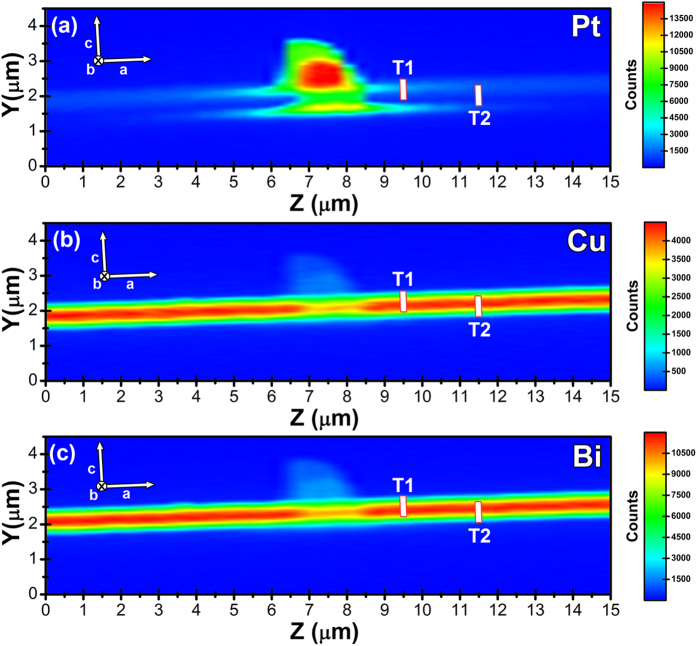
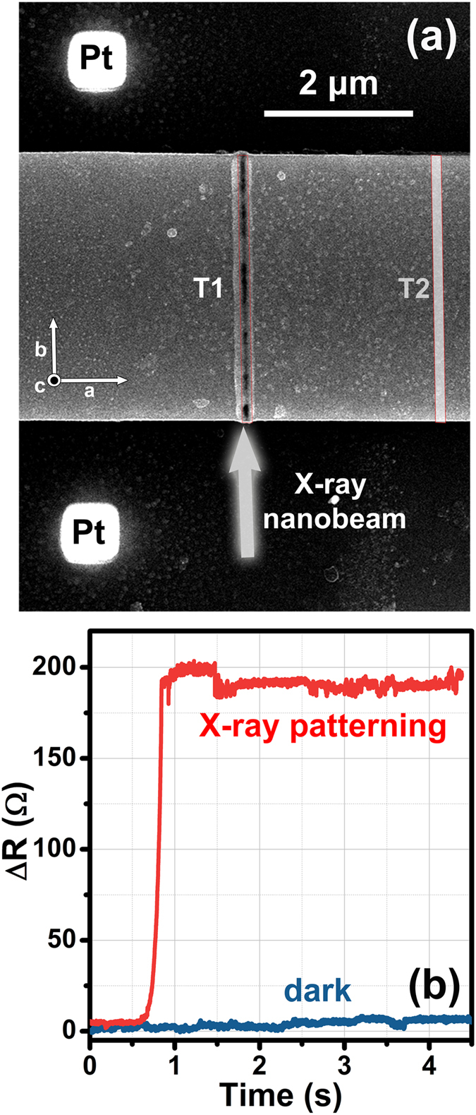
X-ray nanofabrication has so far been usually limited to mask methods involving photoresist impression and subsequent etching. Herein we show that an innovative maskless X-ray nanopatterning approach allows writing electrical devices with nanometer feature size. In particular we fabricated a Josephson device on a Bi2Sr2CaCu2O8+δ (Bi-2212) superconducting oxide micro-crystal by drawing two single lines of only 50 nm in width using a 17.4 keV synchrotron nano-beam. A precise control of the fabrication process was achieved by monitoring in situ the variations of the device electrical resistance during X-ray irradiation, thus finely tuning the irradiation time to drive the material into a non-superconducting state only in the irradiated regions, without significantly perturbing the crystal structure. Time-dependent finite element model simulations show that a possible microscopic origin of this effect can be related to the instantaneous temperature increase induced by the intense synchrotron picosecond X-ray pulses. These results prove that a conceptually new patterning method for oxide electrical devices, based on the local change of electrical properties, is actually possible with potential advantages in terms of heat dissipation, chemical contamination, miniaturization and high aspect ratio of the devices.


Conflict of interest statement

The authors declare that they have no competing interests.

Figures

Figure 1
Figure 1
(a) Photograph of the experimental setup employed at the ESRF ID16B beamline showing the alignment optical microscope, the XRF detectors and the sample rotation stage around the z-axis of the laboratory reference frame. The inset reports a magnification of the sample holder used for the on-line electrical measurements: the chip containing the Bi-2212 micro-crystal is visible in the center of the sample holder. (b) Scanning electron microscope (SEM) image of a Bi-2212 micro-crystal mounted on the chip for electrical characterization. The voltage and current Ag electrodes for the on-line four-probes electrical measurements are labeled as V+, V, I+ and I, respectively. The Pt pillars used for the alignment are visible between the voltage electrodes. (c) Schematic representation of the modifications induced by the trenches in the path of the superconducting current, designed to force it along the c-axis of the Bi-2212 micro-crystal across a stack of intrinsic Josephson junctions. The reference systems present in all the panels show the relative orientation of the laboratory frame (x, y and z) and the Bi-2212 crystal axes (a, b and c). The grey arrow represents the X-ray nano-beam.
Figure 2
Figure 2
Spatial maps of the integrated XRF counts for Pt Lα (a), Cu Kα (b), and Bi Lβ (c) emission lines. The white rectangles highlight the regions which have been irradiated to realize the first (T1) and second (T2) trenches. The beam is parallel to the [0 1 0] crystallographic direction.
Figure 3
Figure 3
(a) SEM image of the Bi-2212 micro-crystal after X-ray irradiation. The white arrow represents the X-ray nano-beam, parallel to the [0 1 0] crystallographic direction, employed to write the two trenches highlighted by red contours. The area irradiated to realize the first trench (T1) is clearly visible, while the area patterned for the second trench (T2), located in the bottom part of the crystal (see also Fig. 2), is highlighted by a white rectangle. (b) Variation of the electrical resistance of the sample measured on-line during the X-ray exposure to write the T1 trench (red curve). The blue curve represents the initial sample resistance immediately before the X-ray nanopatterning procedure: its behaviour is indicative of the environmental electrical noise in the on-line measurement setup.
Figure 4
Figure 4
(a) Comparison of resistance versus temperature measured in the four-probe configuration between pristine (blue curve) and patterned (red curve) conditions. (b) I–V characteristics of a patterned device measured at 58.6 K (red curve), 60.5 K (orange curve) and 62.7 K (blue curve). The red arrows highlight the typical hysteretic pattern in the case of T = 58.6 K. The maximum current amplitudes I c for the three different temperatures are also indicated.
Figure 5
Figure 5
(a) Temporal evolution of the heating power density Q at the beam incidence point (the experiment was performed in 16-bunch filling mode). (b) Corresponding temporal evolution of the sample temperature calculated at the point of maximum temperature. The initial temperature of the system was set to 300 K.

Similar articles

Cited by

References

    1. Seisyan RP. Nanolithography in microelectronics: A review. Tech. Phys. 2011;56:1061–1073. doi: 10.1134/S1063784211080214. - DOI
    1. Marmiroli B, Amenitsch H. X-ray lithography and small-angle X-ray scattering: a combination of techniques merging biology and materials science. Eur. Biophys. J. Biophys. Lett. 2012;41:851–861. doi: 10.1007/s00249-012-0843-3. - DOI - PubMed
    1. Romanato F, et al. Fabrication of 3D metallic photonic crystals by X-ray lithography. Microelectron. Eng. 2003;67-8:479–486. doi: 10.1016/S0167-9317(03)00104-7. - DOI
    1. Maldonado JR, Peckerar M. X-ray lithography: Some history, current status and future prospects. Microelectron. Eng. 2016;161:87–93. doi: 10.1016/j.mee.2016.03.052. - DOI
    1. Cerrina F. X-ray imaging: applications to patterning and lithography. J. Phys. D-Appl. Phys. 2000;33:R103–R116. doi: 10.1088/0022-3727/33/12/201. - DOI

Publication types