. 2017 Aug 25;7(1):9416.
doi: 10.1038/s41598-017-10060-3.

In situ repair of bone and cartilage defects using 3D scanning and 3D printing

Affiliations

In situ repair of bone and cartilage defects using 3D scanning and 3D printing

Lan Li et al. Sci Rep. .

Abstract

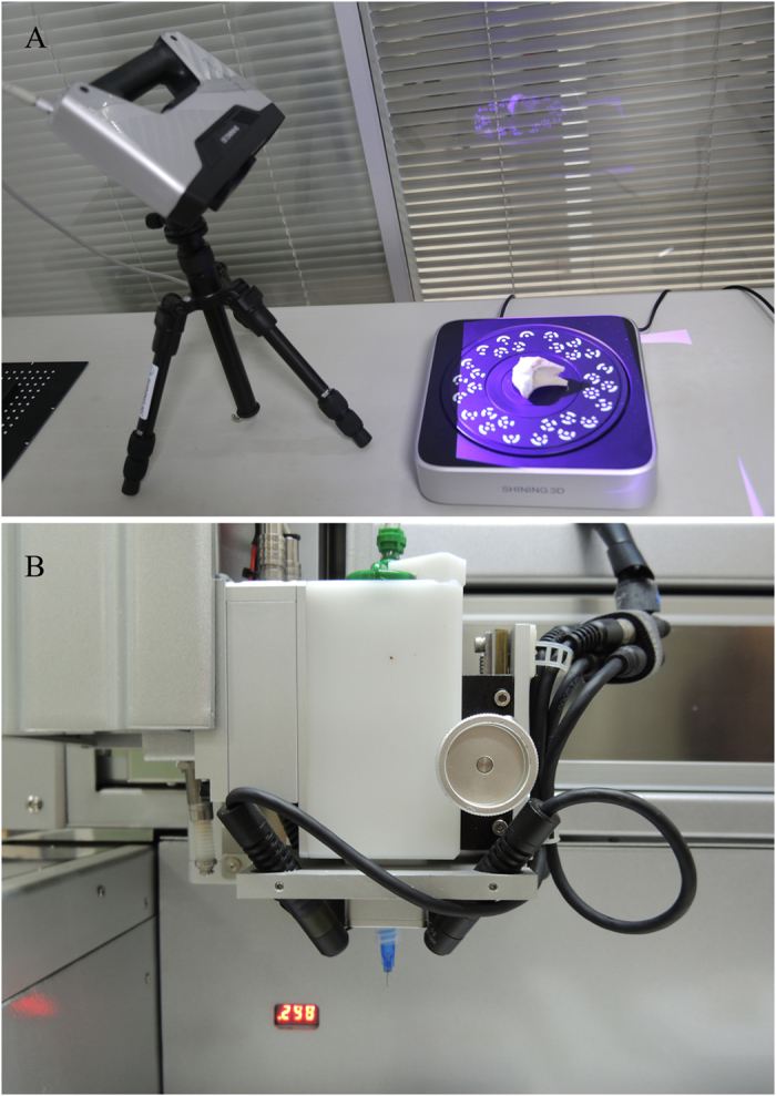
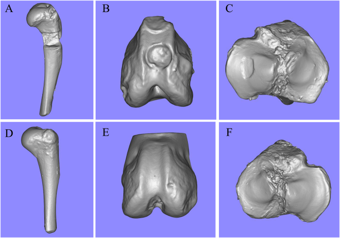
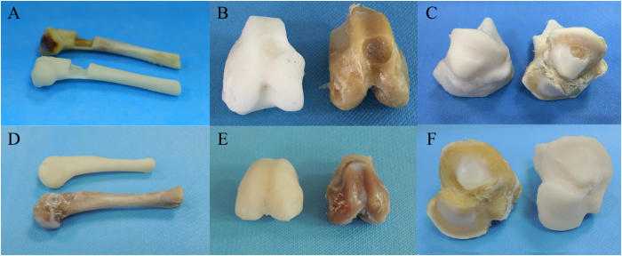
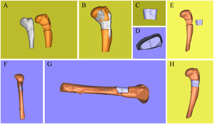
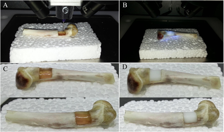
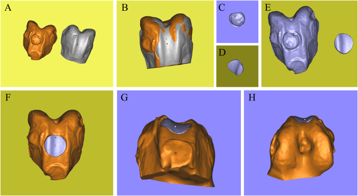
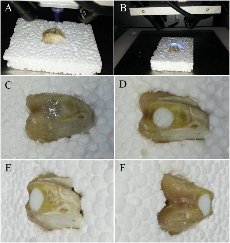
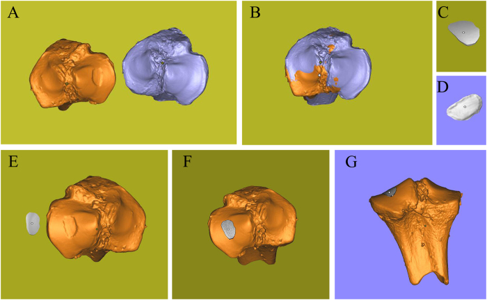
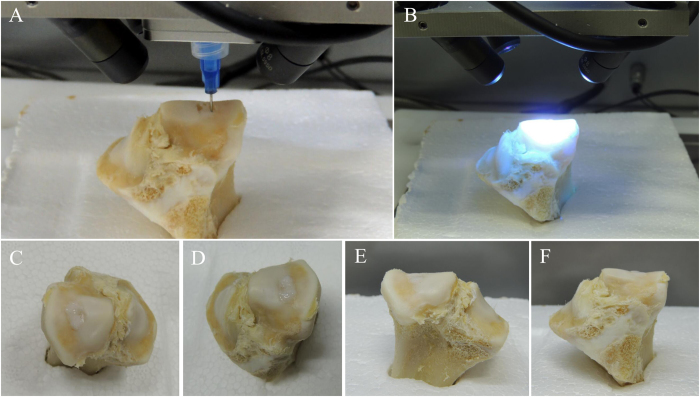
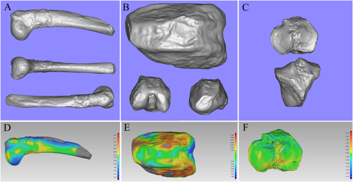
Three-dimensional (3D) printing is a rapidly emerging technology that promises to transform tissue engineering into a commercially successful biomedical industry. However, the use of robotic bioprinters alone is not sufficient for disease treatment. This study aimed to report the combined application of 3D scanning and 3D printing for treating bone and cartilage defects. Three different kinds of defect models were created to mimic three orthopedic diseases: large segmental defects of long bones, free-form fracture of femoral condyle, and International Cartilage Repair Society grade IV chondral lesion. Feasibility of in situ 3D bioprinting for these diseases was explored. The 3D digital models of samples with defects and corresponding healthy parts were obtained using high-resolution 3D scanning. The Boolean operation was used to achieve the shape of the defects, and then the target geometries were imported in a 3D bioprinter. Two kinds of photopolymerized hydrogels were synthesized as bioinks. Finally, the defects of bone and cartilage were restored perfectly in situ using 3D bioprinting. The results of this study suggested that 3D scanning and 3D bioprinting could provide another strategy for tissue engineering and regenerative medicine.


Conflict of interest statement

The authors declare that they have no competing interests.

Figures

Figure 1
Figure 1
Process of 3D scanning and nozzle of the 3D bioprinter. (A) 3D scanning process of tibial plateau. We have been authorized by the owner to use the logo in this figure. (B) Nozzle of the 3D bioprinter was modified with four long-wave UV lights.
Figure 2
Figure 2
Digital models of six samples obtained by 3D handheld scanner. (A,D) Bone defect model and a healthy sample of the contralateral side. (B,E) Osteochondral defect model and a healthy sample of the contralateral side. (C,F) Chondral defect model and a healthy sample of the contralateral side.
Figure 3
Figure 3
Photosensitive resin models of scanning data. (A,D) Comparison of original humeral bones and resin models. (B,E) Comparison of femoral condyles and resin models. (C,F) Comparison of tibial plateau and resin models.
Figure 4
Figure 4
Three-dimensional digital models of humeral bones. (A) Humeral bone digital models with and without defect. (B) Matching of two digital models and using Boolean operation. (C) Frontal view of printing geometry. (D) Lateral view of printing geometry. (E) Frontal view of bone defect model and printing geometry. (F) Left side view of assembly drawing. (G) Right side view of assembly drawing. (H) Frontal view of assembly drawing.
Figure 5
Figure 5
Process of 3D bioprinting and photopolymerization on bone defect. Due to the influence of UV light of camera, the light was turned off when shooting video and photographs in one of the three printing process. Photopolymerization was taken at the end of printing. (A) Repair of bone defect through in situ 3D bioprinting with alginate hydrogel. (B) Exposure to UV light. (C) Alginate hydrogel that was printed to repair the bone defect was transparent before photopolymerization. (D) The color of alginate hydrogel turned milky white after being exposing to UV light in few seconds. The bone defect was restored perfectly.
Figure 6
Figure 6
Three-dimensional digital models of femoral condyle. (A) Femoral condyle digital models with and without defect. (B) Matching of two digital models and using Boolean operation. (C) Posterior view of printing geometry. (D) Frontal view of printing geometry. (E) Frontal view of osteochondral defect model and printing geometry. (F) Frontal view of assembly drawing. (G) Posterior view of assem bly drawing. (H) Anterior view of assembly drawing.
Figure 7
Figure 7
Process of 3D bioprinting and photopolymerization on osteochondral defect. Due to the influence of UV light of camera, the light was turned off when shooting video and photographs in one of the three printing process. Photopolymerization was taken at the end of printing. (A) Repair of osteochondral defect through in situ 3D bioprinting with alginate hydrogel. (B) Exposure to UV light. (C) Alginate hydrogel that was printed to repair the osteochondral defect was transparent before photopolymerization. (DF) The color of alginate hydrogel turned milky white after being exposing to UV light in few seconds. The cartilage cap was slightly higher than the contour of the condyle according to the three views of samples.
Figure 8
Figure 8
Three-dimensional digital models of tibial plateau. (A) Tibial plateau models with and without defect. (B) Matching of two digital models and using Boolean operation. (C) Frontal view of printing geometry. (D) Posterior view of printing geometry. (E) Frontal view of bone defect model and printing geometry. (F) Frontal view of assembly drawing. (G) Anterior view of assembly drawing.
Figure 9
Figure 9
Process of 3D bioprinting and photopolymerization on chondral defect. Due to the influence of UV light of camera, the light was turned off when shooting video and photographs in one of the three printing process. Photopolymerization was taken at the end of printing. (A) Repair of chondral defect through in situ 3D bioprinting with m-HA hydrogel. (B) Exposure to UV light. (CF) The color of m-HA hydrogel that was printed to repair the chondral defect was milky white before and after photopolymerization. The chondral defect was restored perfectly.
Figure 10
Figure 10
Measurement of in situ 3D bioprinting. (A) 3D model of the repaired bone defect. (B) 3D model of the repaired osteochondral defect. (C) 3D model of the repaired chondral defect. (D) Result of 3D Samples Comparison on bone defect. The major color on the surface of were green and yellow, and the partial boundary was blue. (E) Result of 3D Samples Comparison on osteochondral defect. The major color on the surface of was green, and the bilateral boundary were yellow and light red. (F) Result of 3D Samples Comparison on chondral defect. The major color on the surface of were green and yellow. The boundary was green and the central region was yellow.

References

    1. Seol YJ, Kang HW, Lee SJ, Atala A, Yoo JJ. Bioprinting technology and its applications. Eur J Cardiothorac Surg. 2014;46:342–348. doi: 10.1093/ejcts/ezu148. - DOI - PubMed
    1. Fedorovich NE, Alblas J, Hennink WE, Oner FC, Dhert WJ. Organ printing: the future of bone regeneration? Trends Biotechnol. 2011;29:601–606. doi: 10.1016/j.tibtech.2011.07.001. - DOI - PubMed
    1. Duan B, Hockaday LA, Kang KH, Butcher JT. 3D Bioprinting of heterogeneous aortic valve conduits with alginate/gelatin hydrogels †. Journal of Biomedical Materials Research Part A. 2013;101A:1255–1264. doi: 10.1002/jbm.a.34420. - DOI - PMC - PubMed
    1. Norotte C, Marga FS, Niklason LE, Forgacs G. Scaffold-free vascular tissue engineering using bioprinting. Biomaterials. 2009;30:5910–5917. doi: 10.1016/j.biomaterials.2009.06.034. - DOI - PMC - PubMed
    1. Fedorovich NE, De Wijn JR, Verbout AJ, Alblas J, Dhert WJ. Three-dimensional fiber deposition of cell-laden, viable, patterned constructs for bone tissue printing. Tissue Engineering Part A. 2008;14:127–133. doi: 10.1089/ten.a.2007.0158. - DOI - PubMed

Publication types