

Mechanical, chemical and biological damage modes within head-neck tapers of CoCrMo and Ti6Al4V contemporary hip replacements
- PMID: 28842959
- PMCID: PMC5826871
- DOI: 10.1002/jbm.b.33972
Mechanical, chemical and biological damage modes within head-neck tapers of CoCrMo and Ti6Al4V contemporary hip replacements
Abstract
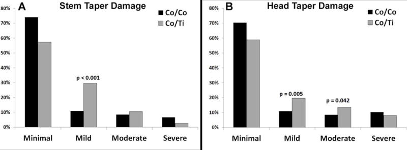
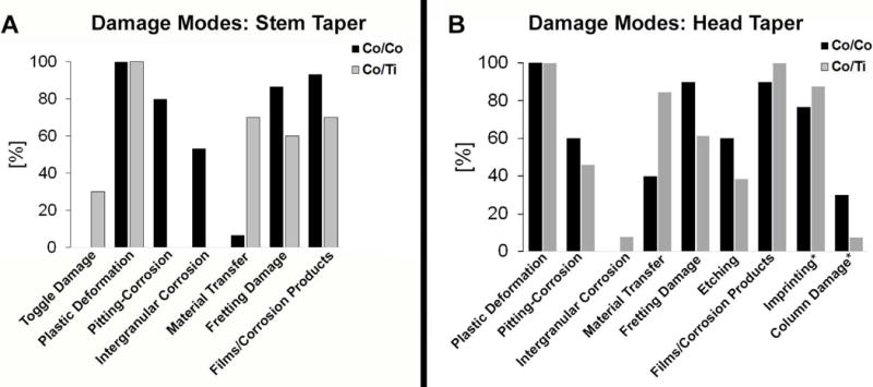
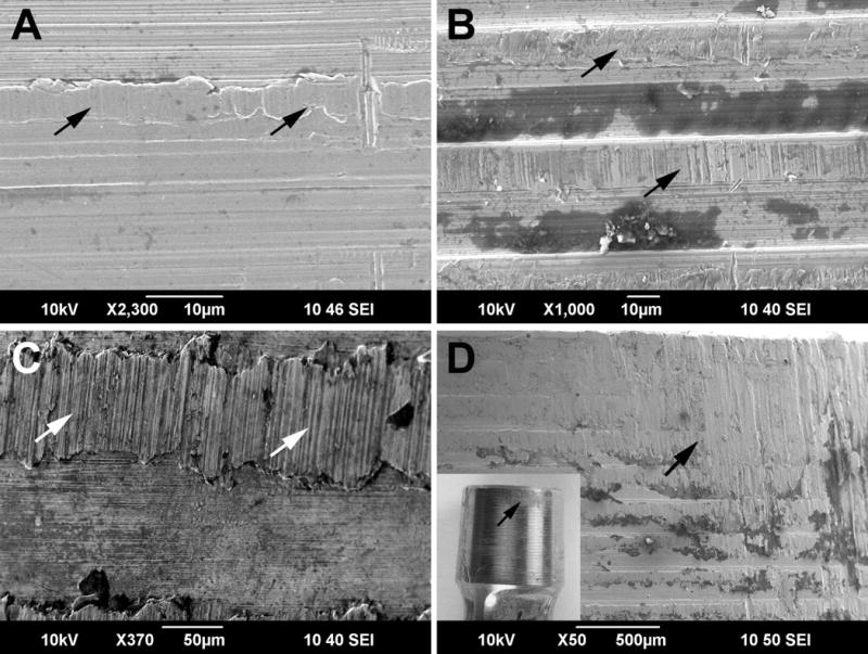
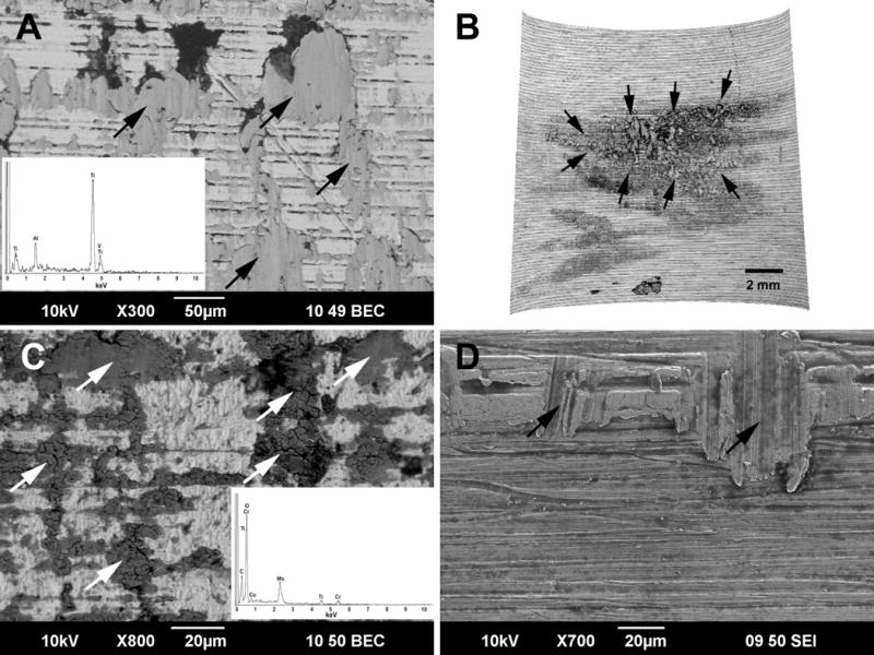
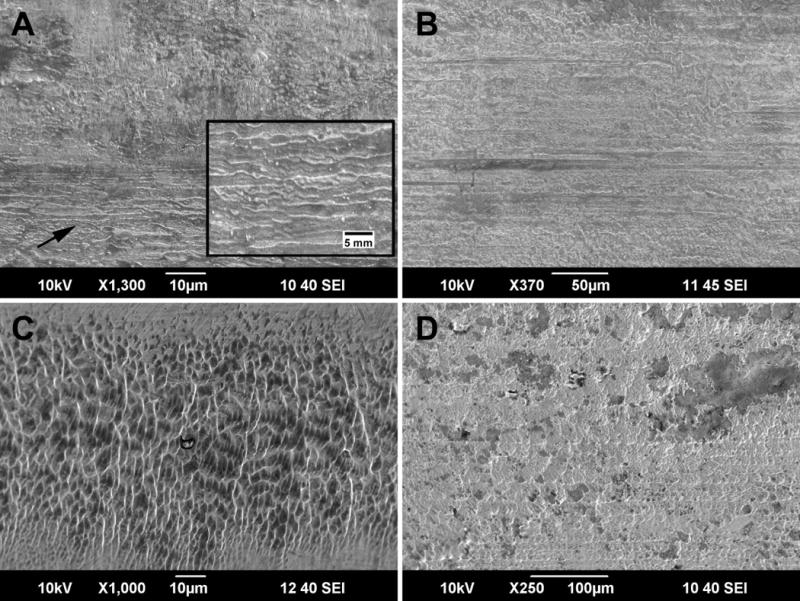
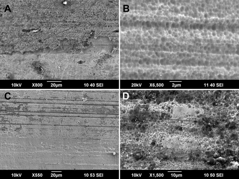
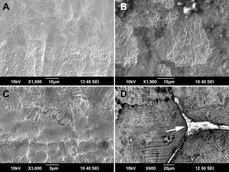
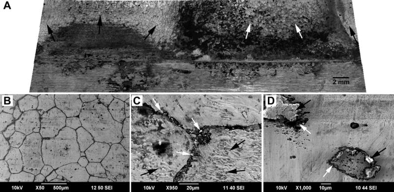
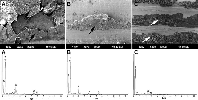
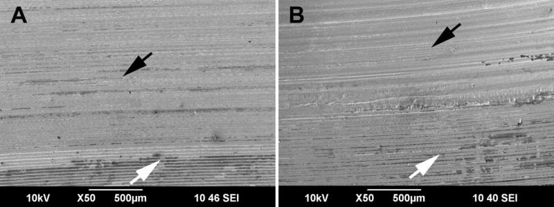
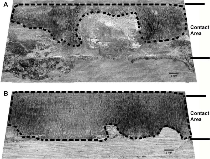
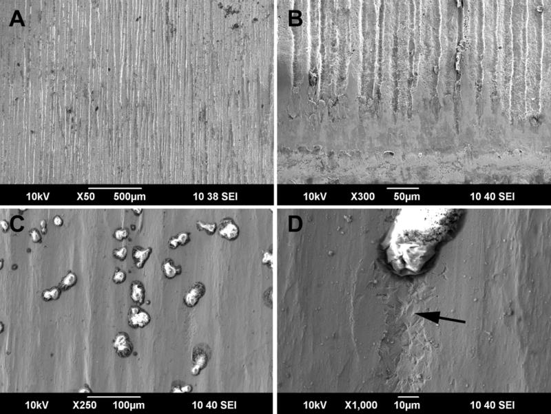
Total hip replacement (THR) failure due to mechanically assisted crevice corrosion within modular head-neck taper junctions remains a major concern. Several processes leading to the generation of detrimental corrosion products have been reported in first generation modular devices. Contemporary junctions differ in their geometries, surface finishes, and head alloy. This study specifically provides an overview for CoCrMo/CoCrMo and CoCrMo/Ti6Al4V head-neck contemporary junctions. A retrieval study of 364 retrieved THRs was conducted which included visual examination and determination of damage scores, as well as the examination of damage features using scanning electron microscopy. Different separately occurring or overlapping damage modes were identified that appeared to be either mechanically or chemically dominated. Mechanically dominated damage features included plastic deformation, fretting, and material transfer, whereas chemically dominate damage included pitting corrosion, etching, intergranular corrosion, phase boundary corrosion, and column damage. Etching associated cellular activity was also observed. Furthermore, fretting corrosion, formation of thick oxide films, and imprinting were observed which appeared to be the result of both mechanical and chemical processes. The occurrence and extent of damage caused by different modes was shown to depend on the material, the material couple, and alloy microstructure. In order to minimize THR failure due to material degradation within modular junctions, it is important to distinguish different damage modes, determine their cause, and identify appropriate counter measures, which may differ depending on the material, specific microstructural alloy features, and design factors such as surface topography. © 2017 Wiley Periodicals, Inc. J Biomed Mater Res Part B: Appl Biomater, 106B: 1672-1685, 2018.
Keywords: corrosion; electron microscopy; fretting; implant retrieval; joint replacement.
© 2017 Wiley Periodicals, Inc.
Conflict of interest statement
Conflict of Interest:
Deborah J. Hall: Consultant -Wright Medical; Research and Institutional Support -Wright Medical, Zimmer, AgNovos Healthcare
Joshua J. Jacobs: Stock Options -Implant Protection; Research and Institutional Support -Medtronic Sofamor Danek, NuVasive, Zimmer
Robert M. Urban: Consultant -Wright Medical, Intrinsic Therapeutics, Exactech, AgNovos Healthcare, Smith & Nephew; Research and Institutional Support -NIH, Wright Medical, Zimmer, AgNovos Healthcare, OREF
Figures
Similar articles
-
Are Damage Modes Related to Microstructure and Material Loss in Severely Damaged CoCrMo Femoral Heads?Clin Orthop Relat Res. 2021 Sep 1;479(9):2083-2096. doi: 10.1097/CORR.0000000000001819. Clin Orthop Relat Res. 2021. PMID: 34019490 Free PMC article.
-
Insights into Imprinting: How Is the Phenomenon of Tribocorrosion at Head-Neck Taper Interfaces Related to Corrosion, Fretting, and Implant Design Parameters?Clin Orthop Relat Res. 2022 Aug 1;480(8):1585-1600. doi: 10.1097/CORR.0000000000002202. Epub 2022 Apr 5. Clin Orthop Relat Res. 2022. PMID: 35383614 Free PMC article.
-
Effect of impact assembly on the interface deformation and fretting corrosion of modular hip tapers: An in vitro study.J Orthop Res. 2018 Jan;36(1):405-416. doi: 10.1002/jor.23601. Epub 2017 Jun 26. J Orthop Res. 2018. PMID: 28485507
-
Corrosion at the head-neck interface of current designs of modular femoral components: essential questions and answers relating to corrosion in modular head-neck junctions.Bone Joint J. 2016 May;98-B(5):579-84. doi: 10.1302/0301-620X.98B5.35592. Bone Joint J. 2016. PMID: 27143725 Review.
-
Evidence based recommendations for reducing head-neck taper connection fretting corrosion in hip replacement prostheses.Hip Int. 2017 Nov 21;27(6):523-531. doi: 10.5301/hipint.5000545. Epub 2017 Oct 9. Hip Int. 2017. PMID: 29027189 Review.
Cited by
-
Mechanistic insight on the combined effect of albumin and hydrogen peroxide on surface oxide composition and extent of metal release from Ti6Al4V.J Biomed Mater Res B Appl Biomater. 2019 Apr;107(3):858-867. doi: 10.1002/jbm.b.34182. Epub 2018 Aug 13. J Biomed Mater Res B Appl Biomater. 2019. PMID: 30102828 Free PMC article.
-
Fretting-corrosion in hip taper modular junctions: The influence of topography and pH levels - An in-vitro study.J Mech Behav Biomed Mater. 2021 Jun;118:104443. doi: 10.1016/j.jmbbm.2021.104443. Epub 2021 Mar 12. J Mech Behav Biomed Mater. 2021. PMID: 33752094 Free PMC article.
-
Model validation for estimating taper microgroove deformation during total hip arthroplasty head-neck assembly.J Biomech. 2022 Jul;140:111172. doi: 10.1016/j.jbiomech.2022.111172. Epub 2022 Jun 3. J Biomech. 2022. PMID: 35696772 Free PMC article.
-
Performance of Austenitic High-Nitrogen Steels under Gross Slip Fretting Corrosion in Bovine Serum.J Funct Biomater. 2024 Apr 18;15(4):110. doi: 10.3390/jfb15040110. J Funct Biomater. 2024. PMID: 38667567 Free PMC article.
-
Modelling changes in modular taper micromechanics due to surgeon assembly technique in total hip arthroplasty.Bone Joint J. 2020 Jul;102-B(7_Supple_B):33-40. doi: 10.1302/0301-620X.102B7.BJJ-2019-1678.R1. Bone Joint J. 2020. PMID: 32600210 Free PMC article.
References
-
- Kurtz SM, Ong KL, Lau E, Bozic KJ. Impact of the economic downturn on total joint replacement demand in the United States: updated projections to 2021. J Bone Joint Surg Am. 2014;96(8):624–630. - PubMed
-
- Jacobs JJ, Cooper HJ, Urban RM, et al. What do we know about taper corrosion in total hip arthroplasty? J Arthroplasty. 2014;29(4):668–669. - PubMed
-
- Carli A, Reuven A, Zukor DJ, Antoniou J. Adverse soft-tissue reactions around non-metal-on-metal total hip arthroplasty - a systematic review of the literature. Bull NYU Hosp Joint Dis. 2011;69(Suppl 1):S47–51. - PubMed
-
- Lindgren JU, Brismar BH, Wikstrom AC. Adverse reaction to metal release from a modular metal-on-polyethylene hip prosthesis. J Bone Joint Surg Br. 2011;93(10):1427–1430. - PubMed
Publication types
MeSH terms
Substances
Grants and funding
LinkOut - more resources
Full Text Sources
Other Literature Sources
Medical
