. 2017 Apr-Jun;89(2):025006.
doi: 10.1103/RevModPhys.89.025006. Epub 2017 Jun 5.

Interface-Induced Phenomena in Magnetism

Affiliations

Interface-Induced Phenomena in Magnetism

Frances Hellman et al. Rev Mod Phys. 2017 Apr-Jun.

Abstract

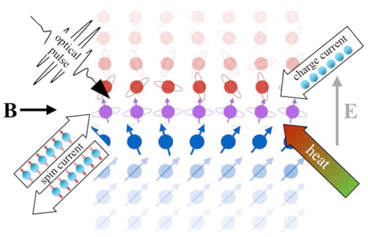
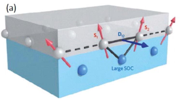
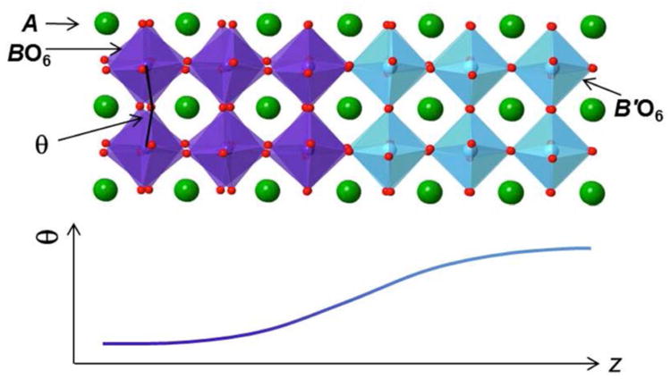
This article reviews static and dynamic interfacial effects in magnetism, focusing on interfacially-driven magnetic effects and phenomena associated with spin-orbit coupling and intrinsic symmetry breaking at interfaces. It provides a historical background and literature survey, but focuses on recent progress, identifying the most exciting new scientific results and pointing to promising future research directions. It starts with an introduction and overview of how basic magnetic properties are affected by interfaces, then turns to a discussion of charge and spin transport through and near interfaces and how these can be used to control the properties of the magnetic layer. Important concepts include spin accumulation, spin currents, spin transfer torque, and spin pumping. An overview is provided to the current state of knowledge and existing review literature on interfacial effects such as exchange bias, exchange spring magnets, spin Hall effect, oxide heterostructures, and topological insulators. The article highlights recent discoveries of interface-induced magnetism and non-collinear spin textures, non-linear dynamics including spin torque transfer and magnetization reversal induced by interfaces, and interfacial effects in ultrafast magnetization processes.


Figures

Figure 1
Figure 1
Interface between a ferromagnet (blue atoms with arrows) and a heavy metal with strong spin-orbit coupling (red atoms with circles). Interface atoms are shown in purple with circles and arrows, schematically indicating interfacial mixing of structure, chemical, magnetic, and electronic states that modify spin and orbital properties on each side, in turn creating new magnetic properties, novel charge and spin transport, and emergent electromagnetic fields. (Time dependent) charge currents, optical pulses, heat, and electric and magnetic fields (directions are illustrative) interact with this heterostructure to produce spin currents, which modify the electronic and magnetic states.
Figure 2
Figure 2
Dependence of the individual orbital spin-orbit coupling strength λnl for atoms as a function of their atomic number Z Calculated results [Herman and Skillman, 1963] using the Hartree-Fock method (solid colored lines) are compared to the hydrogenic Z4 dependence, which is computed for the 3d series (upper dashed line). For the outermost electrons (indicated by the circles and the shaded area), which are the relevant electrons in the solid, the quantum numbers n, l change with Z and the spin-orbit interaction increases much more slowly, following roughly the Landau-Lifshitz Z2 scaling (lower dashed line), although within each series, the dependence remains closer to Z4. Adapted from [Shanavas et al., 2014].
Figure 3
Figure 3
Schematic of the 3-site mechanism for generating an interfacial Dzyaloshinskii-Moriya interaction [Fert et al., 2013]. Spins S1 and S2 in the ferromagnetic (grey, upper) layer couple to each other through overlap of their wave functions with an atom with large spin-orbit coupling (blue, lower layer). This overlap gives rise to a contribution to the energy of the form D12(S1×S2), where D12 lies in the plane of the interface, in the direction normal to the plane defined by the three atoms. These qualitative properties are dictated by symmetry and identical to those predicted by more detailed non-local band models [e.g. Heinze et al., 2011; Dupé et al., 2014].
Figure 4
Figure 4
Schematic of a perovskite ABO3/AB′O3 interface, across which spatial variations in the B-O-B bond angle (θ) can lead to non-bulk-like magnetic behavior. The length scale for coupling of BO6 rotations is typically on the order of 2 to 8 unit cells, depending on the interfaces. The A-site cations and oxide anions are depicted as large green and small red spheres, respectively, while the BO6 (B′O6) octahedra are purple (blue). Similar length scales are commonly observed for interfacial charge transfer at oxide interfaces.
Figure 5
Figure 5
(a) Scanning transmission electron microscopy image of a La05Sr05CoO3-δ film on SrTiO3(001). Note the in-plane structural modulation due to oxygen vacancy ordering (red arrows at top). Image adapted from [Gazquez et al., 2013]. (b) Scanning transmission electron microscopy image of a SrMnO3/LaMnO3 superlattice on SrTiO3. Note the structural asymmetry between the top and bottom interfaces of the LaMnO3 layers (red arrows on right). Image adapted from [May et al., 2008].
Figure 6
Figure 6
Schematic of typical spin-orbit torque (dominated by antidamping-like torque of Eq. 3.3). (a) Charge current j flows in -direction in a strongly spin-orbit-coupled non-magnetic metal (here, Ta) (large white arrow shows electron flow along − with electrons represented as gold spheres), creating a bulk spin Hall effect (±ŷ-polarized spin moments (opposite to the ∓ŷ spin direction), shown with small dark blue arrows, deflected along ±). This mechanism creates a spin current with spin moments pointing along (=y) (black arrow) that flows along into the ferromagnet (here, a-Co-Fe-B with perpendicular magnetic anisotropy (PMA) and magnetization m) and travels some distance before losing spin-polarization, causing spin-orbit torque Tsot (blue vector) that acts on m (gold vector). In response to the onset of current and spin flow, m tilts in the direction of Tsot i.e., towards ŷ, shown in (b). As m tilts away from , Tsot also tilts (shown in b) along the component of perpendicular to m, and a new torque develops due to PMA, Tpma (red vector) (one type of effective field, referred to in Eq. 2.3). Below a critical current (which depends on anisotropy strength), m precesses with decreasing amplitude (dependent on damping constant α) until it reaches a stationary state with m tilted in the x-z plane where the two torques cancel, as shown in (c). At higher current, the stationary state m is along =ŷ. In the absence of an additional symmetry-breaking field (as discussed in the text), m never crosses the x-y plane, i.e., these torques do not lead to magnetization reversal for uniform m.
Figure 7
Figure 7
Schematic of spin pumping from a ferromagnet (Ni81Fe19) film into a nonmagnetic metal (Pt). (a) A microwave field causes precession of magnetization M(t) around the applied external field H, pumping spins into the nonmagnet and generating voltage V through the inverse spin Hall effect. (b) The precessing M(t) pumps spins into the Pt causing spin current Js with spins σ, in the directions shown, equivalent to a net flow of moments (black arrows on electrons) oppositely directed to M. The moving electrons are deflected (to the right, for Pt which has the opposite sign of SHE to Ta) by the inverse spin Hall effect which creates an emergent (effective) electric field Eishe in the direction shown. In an open circuit, shown in (a), the resulting induced transient current causes charge to accumulate at the ends of the sample, indicated by the +/-, giving rise to a real electric field (equal and opposite to Eishe) and the measured voltage V. From [Ando et al., 2011]
Figure 8
Figure 8
Schematic illustrations of (a) conventional Seebeck effect with temperature difference ΔT applied to a metal (hot end on left), electric field E (voltage V) generated along ΔT and (b) conventional Peltier with applied voltage generating a temperature difference. The conventional effects in (a) and (b) are dominated by thermally-induced asymmetric diffusion (indicated by large grey diffusion arrow) of both spin up (red) and spin down (green) electrons in (a), or voltage-induced drift (small black arrows for both spin up and spin down electrons) in (b), though a phonon flux is always present (as indicated schematically) as well as a magnon flux, which can contribute via momentum transfer in drag effects. These are compared to (c) spin Seebeck effect with ΔT applied to a ferromagnet with M into the page (either metal or insulator) which produces a spin current and (d) the reciprocal spin Peltier effect. When connected to a non-magnetic metal (NM, blue), ΔT induces a spin current that is converted into a vertical electric field Eishe and VISHE due to the inverse spin Hall effect. In (c) and (d), magnons in the ferromagnet are shown producing the spin current, but different chemical potentials for up and down spins in a metallic ferromagnet would also produce a spin current if (and only if) the spin diffusion length were comparable to the sample length. For spin Seebeck and spin Peltier effects, clearly distinguishable only in magnetic insulators, schematics show current understanding of the physical mechanism, which is thermally-driven magnons that cause incoherent spin pumping at the interface. Adapted from [Heremans and Boona, 2014].
Figure 9
Figure 9
Longitudinal spin Seebeck effect in the YIG/Pt system. (a) geometry of the experiment [Boona et al., 2014] and (b) data, showing the dependence of the inverse spin Hall effect voltage VISHE on the applied magnetic field H at room temperature [Uchida et al., 2010a].
Figure 10
Figure 10
Spin-dependent Seebeck (panels a-c) and Peltier (panels d-f) effects for conduction electrons: (a) non-local geometry used for observation of spin-dependent Seebeck effect [Boona et al., 2014]; (b) expected spatial dependence of spin-dependent chemical potentials compared to spin diffusion lengths in ferromagnets (FM) and non-magnets (NM) and (c) thermally-driven spin accumulation signal [Slachter et al., 2010]; (d) Structure used for Onsager reciprocal spin-dependent Peltier effect [Boona et al., 2014]; (e) expected spin-dependent chemical potentials for antiparallel alignment of FM elements, clarifying the short length scale probed and (f) current-driven spin-dependent temperature difference [Flipse et al., 2012].
Figure 11
Figure 11
(a) Torques T on a uniform magnetization with direction m. The vector p indicates the direction of spin polarization of the spin current; in “conventional” spin-transfer, this is along Mfixed (see Eq. 3.2) and in spin-orbit torque transfer, this is (see Eq. 3.3) which is in-plane and perpendicular to the charge current. Tfield is the torque associated with Heff (which includes applied field, exchange interaction, anisotropy) and Tdamping is the (conventional) Gilbert damping torque, as described in Eq. 2.3. Teffective-field and Tanti-damping are the field-like and damping-like (sometimes called Slonczewski) parts of the torque associated with spin-transfer or spin-orbit torques, as discussed in Eqs. 3.2 and 3.3; depending on the sign of the charge current producing the torque, Tanti-damping may be directed along or opposite to the conventional damping torque Tdamping. When they are opposite, as shown, Tanti-damping offsets Tdamping, leading to various dynamic behaviors. (b) Left: Hysteretic switching of the resistance of a magnetic tunnel junction (ferromagnet/non-magnetic insulator/ferromagnet) by spin-transfer torque from a direct current. Upper right: energy diagram of spin-transfer torque switching between parallel (P) and antiparallel (AP) states of the two ferromagnets. Lower right: magnetic tunnel junction with in-plane (left cylinder) or perpendicular (right cylinder) magnetic anisotropy can be switched between P and AP configurations using spin-transfer torque; typically one layer has pinned magnetization (Mfixed) while the other can be switched.
Figure 12
Figure 12
(a) In a bilayer of a heavy metal and ferromagnet (e.g., Pt/permalloy (Py)) in which spin torque is created by the spin Hall effect, the charge current density J and the spin current density JS pass through very different areas a and A respectively. (b) High torque efficiency is possible because each electron transfers spin to Py several times, as described in the text.
Figure 13
Figure 13
(a) The Rashba spin-orbit interaction splits the spin-degeneracy of surface or interface state Fermi surfaces. The spin-orientation of a surface band state depends on momentum, and on a given Fermi surface is opposite for opposite momenta because of time-reversal symmetry. An in-plane current increases the occupation probability of states on one side of the Fermi surface and decreases them on the other side, generating a non-equilibrium spin accumulation. If these spins are exchange coupled to an adjacent ferromagnet, they can apply a torque. (b) Topological insulators have an odd number of surface-state Fermi surfaces and in the simplest case, a single Fermi surface. The partial cancellation that occurs between the separate spin-accumulations of weakly spin-split Fermi surfaces in the Rashba interaction case (a) is therefore absent in the topological insulator case (b) and spin accumulations likely larger. In both cases the spin accumulation is required by symmetry to be perpendicular to the current direction, but its sign depends on surface state electronic structure details.
Figure 14
Figure 14
(a) Illustration of formation of the quantum anomalous Hall effect in a 3D TI film. When time-reversal (TR) symmetry is broken by ferromagnetic ordering in a magnetically-doped 3D TI, the Dirac point in the surface band structure is disrupted by opening of a ‘magnetic gap’; the helical spin textured surface states then engender a single chiral edge mode (dashed purple line) characterized by ballistic transport. (b-d) Observation of quantized anomalous Hall effect in thin film V-doped (Bi,Sb)2Te3: when the electron chemical potential is tuned into the magnetic gap via electrostatic gate, the Hall resistance ρyx = h/e2 (to 1 part in 103) and longitudinal sheet resistance ρxx is only a few ohms [Chang et al., 2015b]. Subsequent experiments demonstrated quantization of Hall resistance to 4 parts in 104 [Liu et al., 2016], despite significant magnetic disorder [Lachman et al., 2015].
Figure 15
Figure 15
Lorentz transmission electron microscopy (LTEM) images of B20 FeGe thin films in (a) the helical phase, showing magnetic chirality twinning at a structural twin boundary (A and B regions) and (b) the skyrmion phase induced by 0.1 T magnetic field applied normal to sample plane at 260 K. Color wheel (inset) and white arrows represent the magnetization direction at every point. c) Sample thickness dependence of skyrmion (SkX), helical (H) and ferromagnet (FM) phase diagram in the magnetic field B - temperature T plane. Color bar is the skyrmion density per square micron. [Yu et al., 2011]
Figure 16
Figure 16
Four types of 180° domain walls in materials magnetized up at front of figure and down at back. (a) Bloch left- and right-handed walls, and (b) Néel left- and right-handed walls [Heide et al., 2008].
Figure 17
Figure 17
Topology and chirality of skyrmions and vortices. The heavy metal layer is assumed to be below in order to define chirality. Structures (a)-(f) are skyrmions constructed using the Belavin-Polyakov profile (2D Heisenberg exchange coupling only). (a)-(e) are within a down magnetized background with an up core. (a), (b) are right-handed, left-handed Néel (hedgehog-type) respectively with Nsk=+1; (c), (d) left-handed, right-handed Bloch (vortex-type) respectively with Nsk=+1; (e) Nsk= -1, with no defined chirality (because spin directions and spatial coordinates counter-rotate). (f) is within an up magnetized background with a down core, Nsk=-1, right-handed Néel skyrmion (note that this structure is the same as (a) with all directions reversed). Structures (g) - (j) are magnetic bubbles within a down magnetized background with an extended up core; (g), (h) have Nsk=+1, and left-handed/right handed Bloch walls respectively. (i) has 4 Bloch lines at each of which the in-plane moment reverses, reducing Nsk by 1/2, leading to Nsk =-1 (this structure is sometimes called an anti-skyrmion); (j) has 2 Bloch lines and Nsk=0. Structures (k) and (l) are magnetic vortex and antivortex respectively, both with an up core and m in the x-y plane away from the core and Nsk= ±1/2; both are sometimes called merons.
Figure 18
Figure 18
Schematic merging of two skyrmions. At the merging point the magnetization vanishes at a singular point, the Bloch point (arrow), which acts like the slider of a zipper connecting two vertically-extended skyrmions. [Milde et al., 2013]
Figure 19
Figure 19
Chiral right-handed Néel walls in a [Co/Ni] multilayer with perpendicular magnetic anisotropy on a Pt(111) substrate (layer thicknesss as shown). Images taken with spin-polarized low energy electron microscopy (SPLEEM). Up/down magnetic domains shown in grey/black. Color wheel shows in plane direction of spins, with white arrows clarifying direction of chirality based on angle of spin, at the 180° domain walls [Chen et al., 2013a].
Figure 20
Figure 20
Schematic showing two left-handed chiral Néel domain walls (also called Dzyaloshinskii domain walls) separating a (red) down-domain from two (blue) up-domains in the top ferromagnetic layer (red, blue, and white arrows show directions of spins in this layer) driven by the Slonczewski-like effective field HSL (along ±z at each domain wall, as shown) due to charge current jc (along −x, shown with thick black arrow) and resulting spin Hall effect in the underlying Pt layer, which causes spin current along +z with +y-polarization. This spin current produces oppositely-directed HSL due to oppositely-directed spins in the two domain walls, causing both domain walls to move with velocity vDW along +x. [Emori et al., 2013]
Figure 21
Figure 21
Current induced nucleation and motion of skyrmions. (a), (b) Schematic of the transformation of stripe domains [dark blue extended areas], with chiral Néel domain walls (small light blue arrows) due to DM interactions, into magnetic skyrmions [circular domain in (b)] in perpendicularly-magnetized Ta/a-Co-Fe-B/a-TaOx due to a laterally-inhomogeneous in-plane charge current density [dashed red arrows in (a)] resulting in inhomogeneous spin-orbit torques. (c), (d) Initial and final state of skyrmion generation due to electric charge currents imaged magneto-optically [Jiang et al., 2015]. (e) Scanning tunneling microscopy (STM) image of creation (“writing”) and annihilation (“deleting”) of individual skyrmions in Pd/Fe bilayer on Ir (111) substrate in an applied magnetic field of 3 T at 4 K, using local spin-polarized tunneling currents from the STM tip. Atomic defects in the film pin the skyrmions [Romming et al., 2013]. (f) Micromagnetic simulations of the trajectory of a spin-orbit-torque-driven skyrmion starting from rest, for two values of damping parameter α, showing gyrotropic motion. The strip is 200 nm wide and six images are shown, every 20 ns, for each α.
Figure 22
Figure 22
Different types of spin-torque nano-oscillators. Top: confined geometries with a pillar structure. Bottom: geometries in which current from a point contact excites magnetic dynamics in an unpatterned magnetic free layer.
Figure 23
Figure 23
Fundamental interaction energies and time scales relevant for ultrafast processes. The effective magnetic field associated with the exchange interaction reach 100 T to 1000 T; these fields correspond to the periods of the Larmor precession in the range 30 fs to 300 fs.
Figure 24
Figure 24
(a) Time-resolved magneto-optic response of a nickel thin film after excitation by a femtosecond laser pulse [Koopmans et al., 2005], showing partial loss of magnetic order at sub-picosecond timescales (rM), followed by recovery due to electron-lattice equilibration (τE). A field is applied out-of-plane to cant the magnetization (inset), leading to precessional dynamics at a slower time scale. (b) Example of simulation showing evolution of the magnetization (red, right axis), electron temperature (blue) and lattice temperature (green) [Koopmans et al., 2010]. (c) Schematics of the three-temperature model, showing interactions between spinless electron gas (e), their spins (s) and the lattice (l) after the system is brought out of equilibrium by a laser pulse [Kirilyuk et al., 2010].
Figure 25
Figure 25
Femtosecond x-ray pulses showing optically induced magnetization dynamics. (a) Decay of spin, Sz, and orbital, Lz, moments in CoPd films [Boeglin et al., 2010]. (b) Reversal of Gd 4f and Fe 3d magnetic moments in a-Gd-Fe-Co alloys [Radu et al., 2011].
Figure 26
Figure 26
(a) Time-resolved photoemission can probe the laser-excited hot electron distribution above the Fermi level, EF. Thermalization implies that the electron distribution follows Fermi-Dirac statistics (solid line) and can be described by a temperature, Te. Adapted from [Rhie et al., 2003]. (b) Illustration of electronic scattering processes leading to decay of initially ballistic spin motion. Superdiffusive spin transport (indicated by grey shading in a)) occurs on sub-psec timescales during the crossover from ballistic to diffusive transport. The diffusive regime may also produce spin currents due to resulting temperature gradients (the spin-dependent Seebeck effect, associated with different chemical potentials of up and down spins).
Figure 27
Figure 27
Schematics of experiments showing superdiffusive spin currents. (a) Demagnetization of Fe film by an ultrashort pump pulse injects spin current into adjacent Au layer with its arrival at the Au backside detected by time-resolved magnetic second harmonic generation, discussed in [Melnikov et al., 2011]. (b) Femtosecond demagnetization of the bottom ferromagnetic layer with perpendicular magnetic anisotropy results in spin-torque-induced precession dynamics in the top ferromagnetic layer driven by superdiffusive spin currents, discussed in [Schellekens et al., 2014; Choi et al., 2014]. (c) Optical pumping heterostructures where femtosecond demagnetization of the bottom Co/Pt multilayer affects demagnetization of the top Co/Pt multilayer for metallic (Ru) but not for insulating (NiO) spacer layers, discussed in [Malinowski et al., 2008]; demagnetization also depends on the relative orientation of the two magnetic layers.
Figure 28
Figure 28
All-optical switching: (a) scanning a laser beam across the sample and simultaneously modulating its polarization between left- and right-circular pulses yields a magnetic bit pattern in an amorphous Gd-Fe-Co alloy [Stanciu et al., 2007]; (b) magneto-optical images of a [Co(0.4 nm)/Pt(0.7 nm)]3 multilayer [Lambert et al., 2014] where sweeping a pulsed laser source with circular polarization determines the final state's magnetic orientation.

References

    1. Abarra EN, Takano K, Hellman F, Berkowitz AE. Thermodynamic Measurements of Magnetic Ordering in Antiferromagnetic Superlattices. Phys Rev Lett. 1996;77:3451. - PubMed
    1. Adamo C, et al. Effect of biaxial strain on the electrical and magnetic properties of (001) La0.7Sr0.3MnO3 thin films. Appl Phys Lett. 2009;95:112504.
    1. Aeschlimann M, Bauer M, Pawlik S, Weber W, Burgermeister R, Oberli D, Siegmann HC. Ultrafast spin-dependent electron dynamics in fcc Co. Phys Rev Lett. 1997;79:5158.
    1. Agrawal M, Vasyuchka VI, Serga AA, Kirihara A, Pirro P, Langner T, Jungfleisch MB, Chumak AV, Th Papaioannou E, Hillebrands B. Role of bulk-magnon transport in the temporal evolution of the longitudinal spin-Seebeck effect. Phys Rev B. 2014;89:224414.
    1. Ahn C, et al. Electrostatic modification of novel materials. Rev Mod Phys. 2006;78:1185.