

Feedforward Coordinate Control of a Robotic Cell Injection Catheter
- PMID: 28901195
- PMCID: PMC5680975
- DOI: 10.1177/0963689717720294
Feedforward Coordinate Control of a Robotic Cell Injection Catheter
Abstract
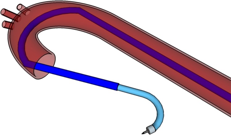
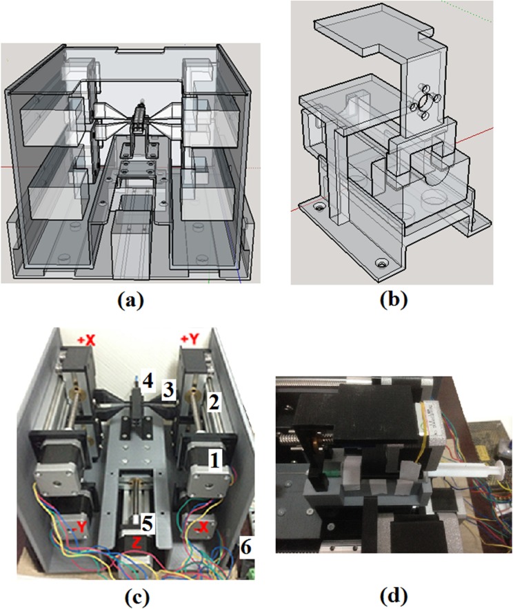
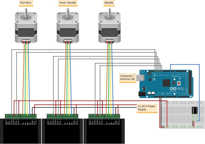
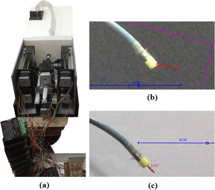
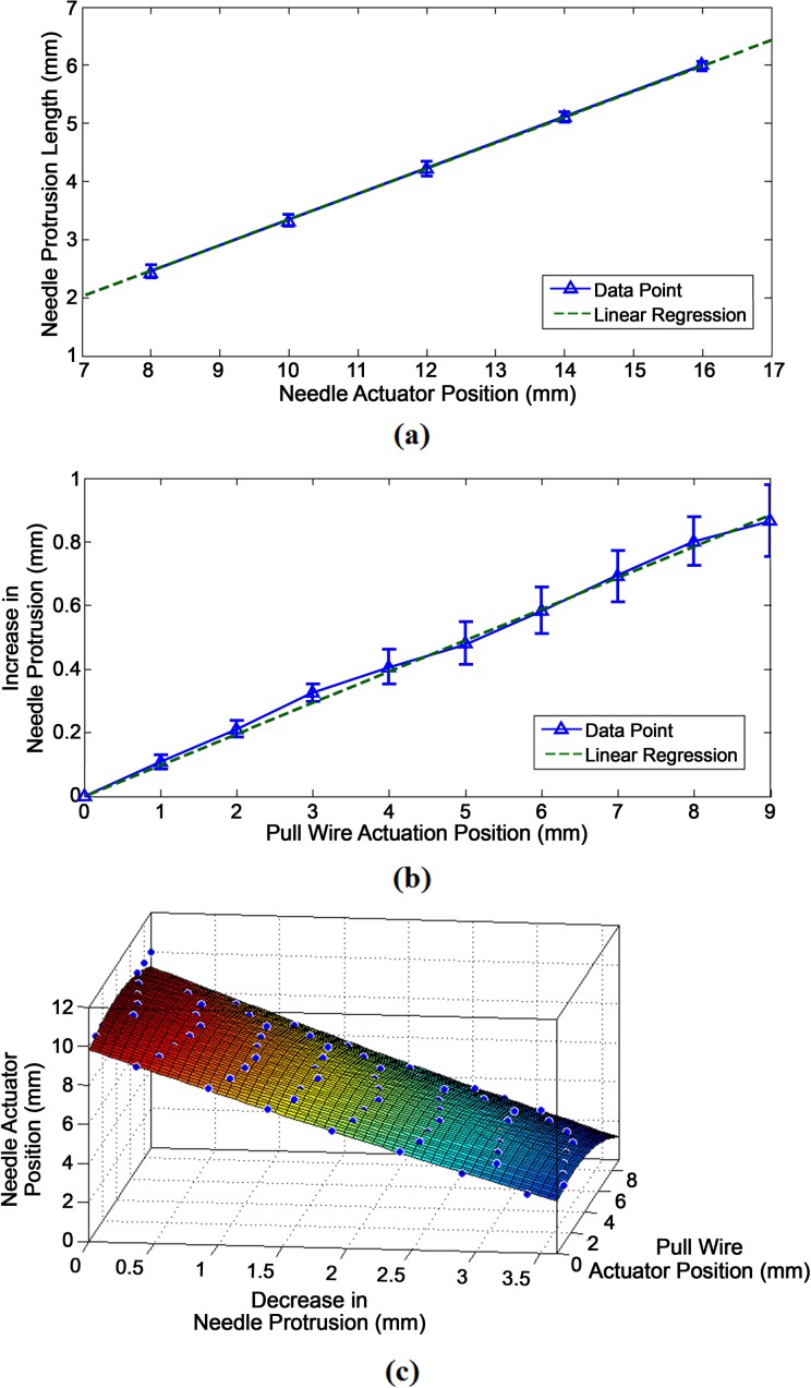
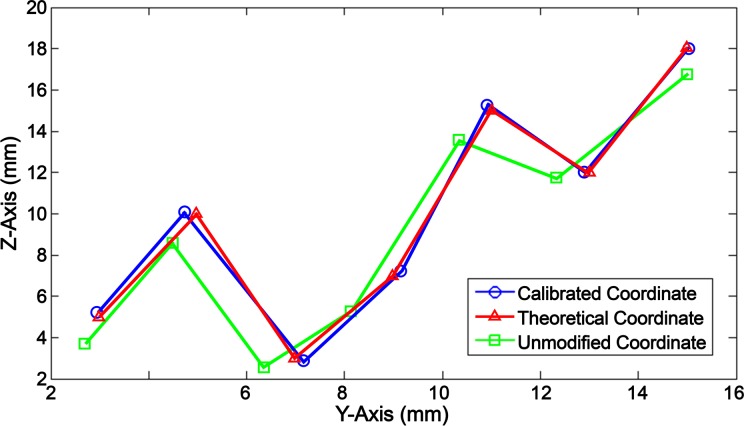
Remote and robotically actuated catheters are the stepping-stones toward autonomous catheters, where complex intravascular procedures may be performed with minimal intervention from a physician. This article proposes a concept for the positional, feedforward control of a robotically actuated cell injection catheter used for the injection of myogenic or undifferentiated stem cells into the myocardial infarct boundary zones of the left ventricle. The prototype for the catheter system was built upon a needle-based catheter with a single degree of deflection, a 3-D printed handle combined with actuators, and the Arduino microcontroller platform. A bench setup was used to mimic a left ventricle catheter procedure starting from the femoral artery. Using Matlab and the open-source video modeling tool Tracker, the planar coordinates ( y, z) of the catheter position were analyzed, and a feedforward control system was developed based on empirical models. Using the Student's t test with a sample size of 26, it was determined that for both the y- and z-axes, the mean discrepancy between the calibrated and theoretical coordinate values had no significant difference compared to the hypothetical value of µ = 0. The root mean square error of the calibrated coordinates also showed an 88% improvement in the z-axis and 31% improvement in the y-axis compared to the unmodified trial run. This proof of concept investigation leads to the possibility of further developing a feedfoward control system in vivo using catheters with omnidirectional deflection. Feedforward positional control allows for more flexibility in the design of an automated catheter system where problems such as systemic time delay may be a hindrance in instances requiring an immediate reaction.
Keywords: catheterization; feedforward systems; intramyocardial injection; numerical models; robotic catheters.
Conflict of interest statement
Figures
Similar articles
-
Conceptual Design and Procedure for an Autonomous Intramyocardial Injection Catheter.Cell Transplant. 2017 May 9;26(5):735-751. doi: 10.3727/096368916X694256. Epub 2016 Dec 7. Cell Transplant. 2017. PMID: 27938487 Free PMC article. Review.
-
Automated Catheter Navigation With Electromagnetic Image Guidance.IEEE Trans Biomed Eng. 2017 Aug;64(8):1972-1979. doi: 10.1109/TBME.2016.2623383. Epub 2017 Mar 2. IEEE Trans Biomed Eng. 2017. PMID: 28362578
-
Electromagnetic tracking of flexible robotic catheters enables "assisted navigation" and brings automation to endovascular navigation in an in vitro study.J Vasc Surg. 2018 Apr;67(4):1274-1281. doi: 10.1016/j.jvs.2017.01.072. Epub 2017 Jun 2. J Vasc Surg. 2018. PMID: 28583735
-
Robotic positioning of standard electrophysiology catheters: a novel approach to catheter robotics.J Invasive Cardiol. 2008 May;20(5):250-3. J Invasive Cardiol. 2008. PMID: 18460712
-
Robotically-steerable catheters and their role in the visceral aortic segment.J Cardiovasc Surg (Torino). 2011 Jun;52(3):353-62. J Cardiovasc Surg (Torino). 2011. PMID: 21577190 Review.
References
-
- Mozaffarian D, Benjamin EJ, Go AS, Arnett DK, Blaha MJ, Cushman M, Das SR, de Ferranti S, Després JP, Fullerton HJ, et al. Heart disease and stroke statistics—2016 update: a report from the American Heart Association. Circulation. 2016;133(4): e38–360. - PubMed
-
- Issa Z, Miller JM, Zipes DP. Advanced mapping and navigation modalities In: Issa Z, Miller JM, Zipes DP, editors. Clinical arrhythmology and electrophysiology: a companion to Braunwald’s heart disease. 2nd ed. Philadelphia (PA): Elsevier; 2012. p. 111–143.
-
- Pappone C, Vicedomini G, Manguso F, Gugliotta F, Mazzone P, Gulletta S, Sora N, Sala S, Marzi A, Augello G, et al. Robotic magnetic navigation for atrial fibrillation ablation. J Am Coll Cardiol. 2006;47(7):1390–1400. - PubMed
-
- Datino T, Arenal A, Pelliza M, Hernández-Hernández J, Atienza F, González-Torrecilla E, Avila P, Bravo L, Fernández-Avilés F. Comparison of the safety and feasibility of arrhythmia ablation using the Amigo robotic remote catheter system versus manual ablation. Am J Cardiol. 2014;113(5):827–831. - PubMed
-
- Horton RP. Remote catheter navigation systems In: Huang SKS, Miller JM, editors. Catheter ablation of cardiac arrhythmias. 3rd ed. Philadelphia (PA): Elsevier Saunders; 2014. p. 153–161.
MeSH terms
LinkOut - more resources
Full Text Sources
Other Literature Sources
