

Optimization of the geometry and speed of a moving blocker system for cone-beam computed tomography scatter correction
- PMID: 28901608
- PMCID: PMC5619659
- DOI: 10.1002/mp.12326
Optimization of the geometry and speed of a moving blocker system for cone-beam computed tomography scatter correction
Abstract
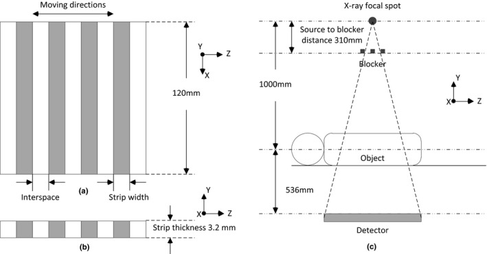
Purpose: X-ray scatter is a significant barrier to image quality improvements in cone-beam computed tomography (CBCT). A moving blocker-based strategy was previously proposed to simultaneously estimate scatter and reconstruct the complete volume within the field of view (FOV) from a single CBCT scan. A blocker consisting of lead stripes is inserted between the X-ray source and the imaging object, and moves back and forth along the rotation axis during gantry rotation. While promising results were obtained in our previous studies, the geometric design and moving speed of the blocker were set empirically. The goal of this work is to optimize the geometry and speed of the moving block system.
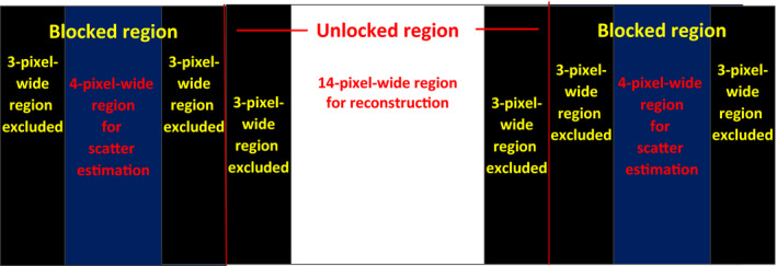
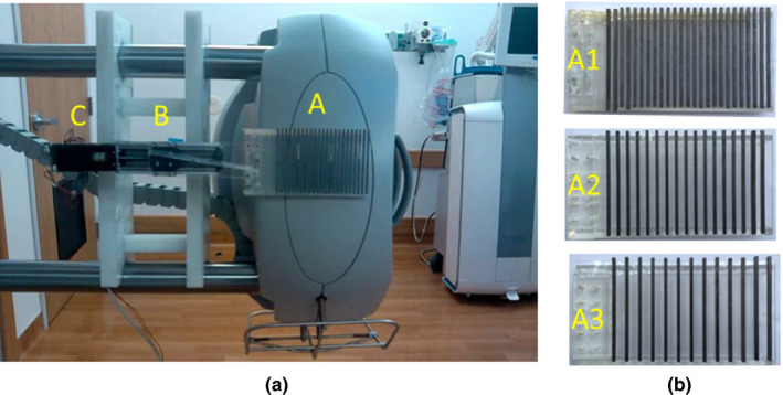
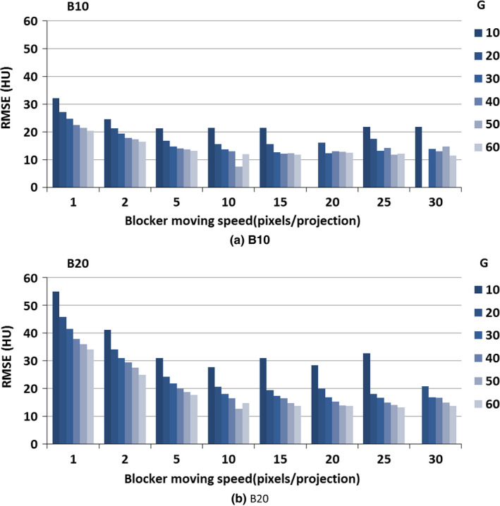
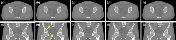
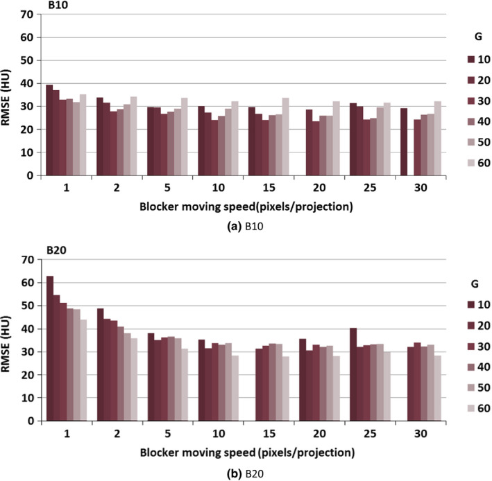
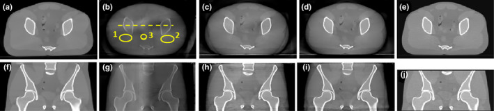
Methods: Performance of the blocker was examined through Monte Carlo (MC) simulation and experimental studies with various geometry designs and moving speeds. All hypothetical designs employed an anthropomorphic pelvic phantom. The scatter estimation accuracy was quantified by using lead stripes ranging from 5 to 100 pixels on the detector plane. An iterative reconstruction based on total variation minimization was used to reconstruct CBCT images from unblocked projection data after scatter correction. The reconstructed image was evaluated under various combinations of lead strip width and interspace (ranging from 10 to 60 pixels) and different moving speed (ranging from 1 to 30 pixels per projection).
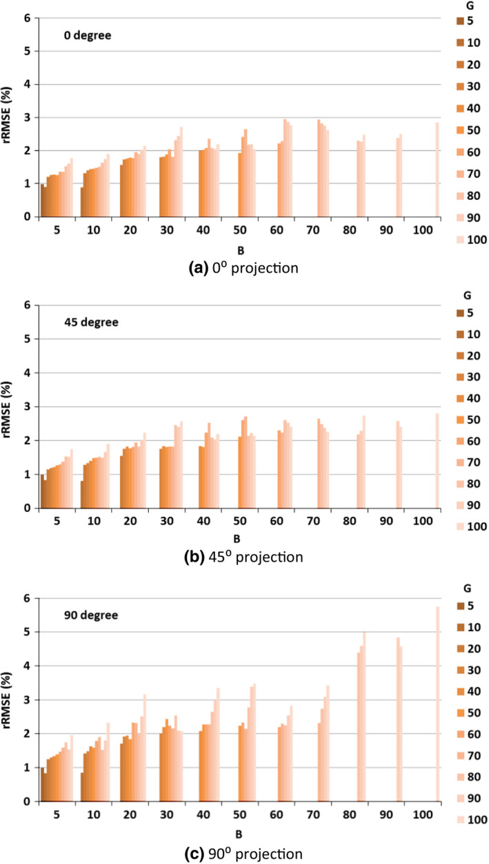
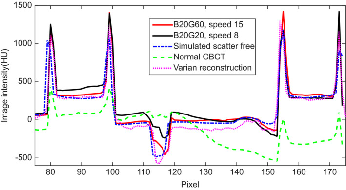
Results: MC simulation showed that the scatter estimation error varied from 0.8% to 5.8%. Phantom experiment showed that CT number error in the reconstructed CBCT images varied from 13 to 35. Highest reconstruction accuracy was achieved when the strip width was 20 pixels and interspace was 60 pixels and the moving speed was 15 pixels per projection.
Conclusions: Scatter estimation can be achieved in a large range of lead strip width and interspace combinations. The moving speed does not have a very strong effect on reconstruction result if it is above 5 pixels per projection. Geometry design of the blocker affected image reconstruction accuracy more. The optimal geometry of the blocker has a strip width of 20 pixels and an interspace three times the strip width, which means 25% detector is covered by the blocker, while the optimal moving speed is 15 pixels per projection.
Keywords: cone-beam CT; imaging artifacts; moving blocker; optimization; scatter correction.
© 2017 American Association of Physicists in Medicine.
Conflict of interest statement
The authors have no relevant conflicts of interest to disclose.
Figures


Similar articles
-
Scatter correction for cone-beam computed tomography using moving blocker strips: a preliminary study.Med Phys. 2010 Nov;37(11):5792-800. doi: 10.1118/1.3495819. Med Phys. 2010. PMID: 21158291
-
A moving blocker system for cone-beam computed tomography scatter correction.Med Phys. 2013 Jul;40(7):071903. doi: 10.1118/1.4811086. Med Phys. 2013. PMID: 23822440
-
Combining scatter reduction and correction to improve image quality in cone-beam computed tomography (CBCT).Med Phys. 2010 Nov;37(11):5634-44. doi: 10.1118/1.3497272. Med Phys. 2010. PMID: 21158275
-
A general framework and review of scatter correction methods in x-ray cone-beam computerized tomography. Part 1: Scatter compensation approaches.Med Phys. 2011 Jul;38(7):4296-311. doi: 10.1118/1.3599033. Med Phys. 2011. PMID: 21859031 Review.
-
Source-detector trajectory optimization in cone-beam computed tomography: a comprehensive review on today's state-of-the-art.Phys Med Biol. 2022 Aug 16;67(16). doi: 10.1088/1361-6560/ac8590. Phys Med Biol. 2022. PMID: 35905731 Review.
Cited by
-
4D cone-beam computed tomography (CBCT) using a moving blocker for simultaneous radiation dose reduction and scatter correction.Phys Med Biol. 2018 May 29;63(11):115007. doi: 10.1088/1361-6560/aac229. Phys Med Biol. 2018. PMID: 29722297 Free PMC article.
-
An unsupervised 2D-3D deformable registration network (2D3D-RegNet) for cone-beam CT estimation.Phys Med Biol. 2021 Mar 24;66(7):10.1088/1361-6560/abe9f6. doi: 10.1088/1361-6560/abe9f6. Phys Med Biol. 2021. PMID: 33631734 Free PMC article.
-
SparseCT: System concept and design of multislit collimators.Med Phys. 2019 Jun;46(6):2589-2599. doi: 10.1002/mp.13544. Epub 2019 May 6. Med Phys. 2019. PMID: 30980728 Free PMC article.
-
Advanced 4-dimensional cone-beam computed tomography reconstruction by combining motion estimation, motion-compensated reconstruction, biomechanical modeling and deep learning.Vis Comput Ind Biomed Art. 2019;2(1):23. doi: 10.1186/s42492-019-0033-6. Epub 2019 Dec 12. Vis Comput Ind Biomed Art. 2019. PMID: 32190409 Free PMC article.
-
Real-time liver tumor localization via combined surface imaging and a single x-ray projection.Phys Med Biol. 2023 Mar 9;68(6):065002. doi: 10.1088/1361-6560/acb889. Phys Med Biol. 2023. PMID: 36731143 Free PMC article.
References
-
- Jaffray DA, Siewerdsen JH, Wong JW, Martinez AA. Flat‐panel cone‐beam computed tomography for image‐guided radiation therapy. Int J Radiat Oncol Biol Phys. 2002;53:1337–1349. - PubMed
-
- Létourneau D, Wong JW, Oldham M, et al. Cone‐beam‐CT guided radiation therapy: technical implementation. Radiother Oncol. 2005;75:279–286. - PubMed
-
- Xing L, Thorndyke B, Schreibmann E, et al. Overview of image‐guided radiation therapy. Med Dosim. 2006;31:91–112. - PubMed
-
- Zhang Y, Yin F‐F, Segars WP, Ren L. A technique for estimating 4D‐CBCT using prior knowledge and limited‐angle projections. Med Phys. 2013;40:121701. - PubMed
-
- Siewerdsen JH, Jaffray DA. Cone‐beam computed tomography with a flat‐panel imager: magnitude and effects of X‐ray scatter. Med Phys. 2001;28:220–231. - PubMed
MeSH terms
Grants and funding
LinkOut - more resources
Full Text Sources
Other Literature Sources
