

Fiber Optic Sensors For Detection of Toxic and Biological Threats
- PMID: 28903282
- PMCID: PMC3841883
- DOI: 10.3390/s7123100
Fiber Optic Sensors For Detection of Toxic and Biological Threats
Abstract
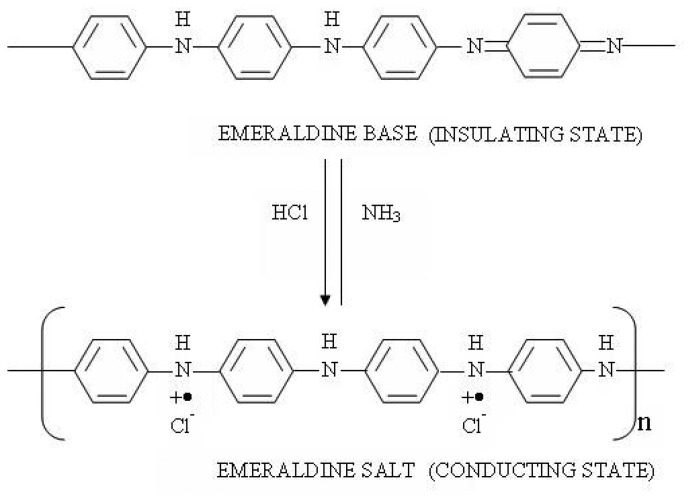
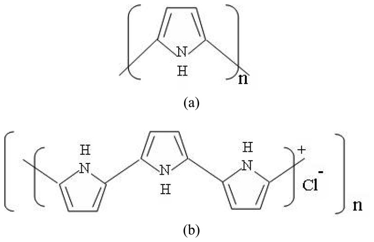
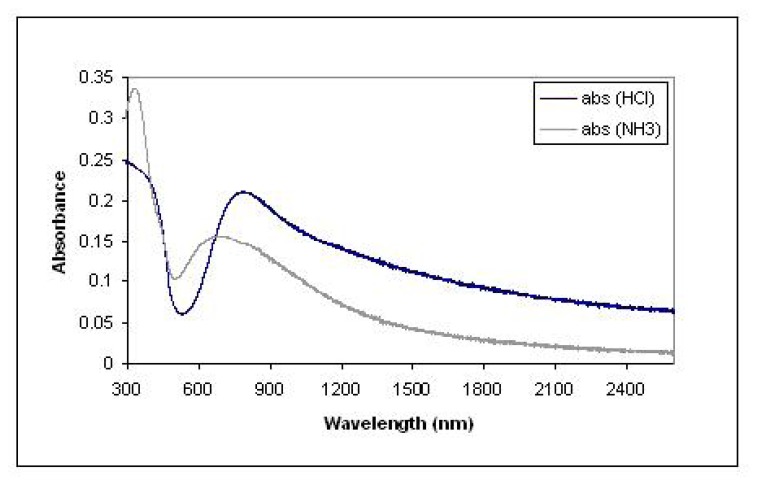
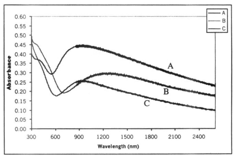
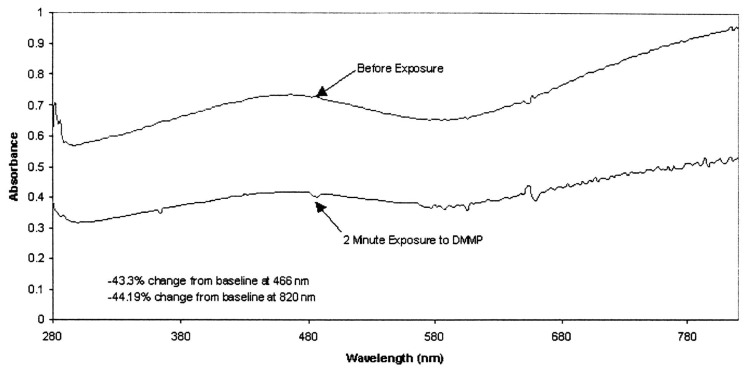
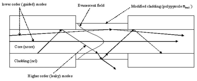
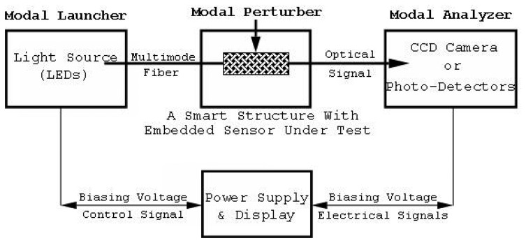
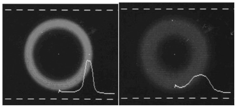
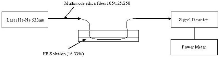
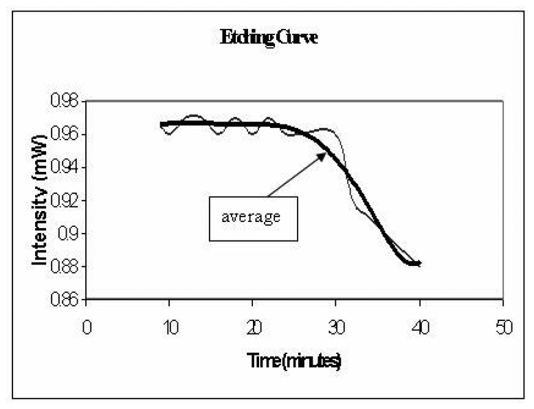
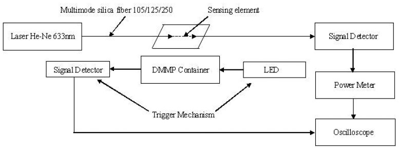
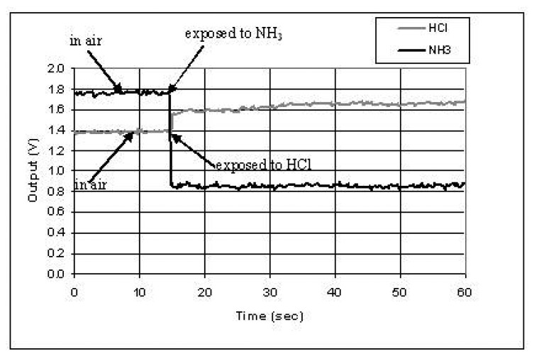
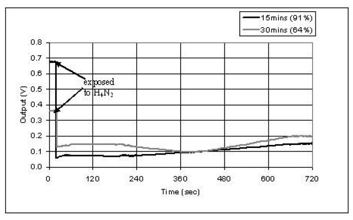
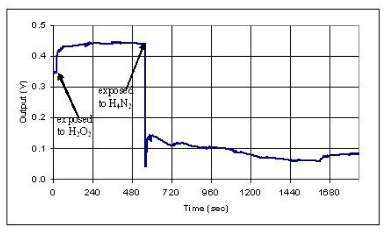
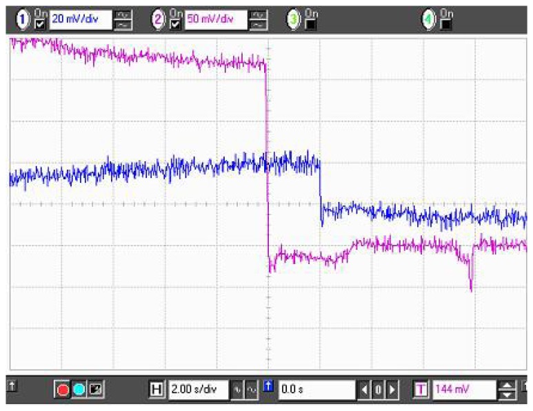
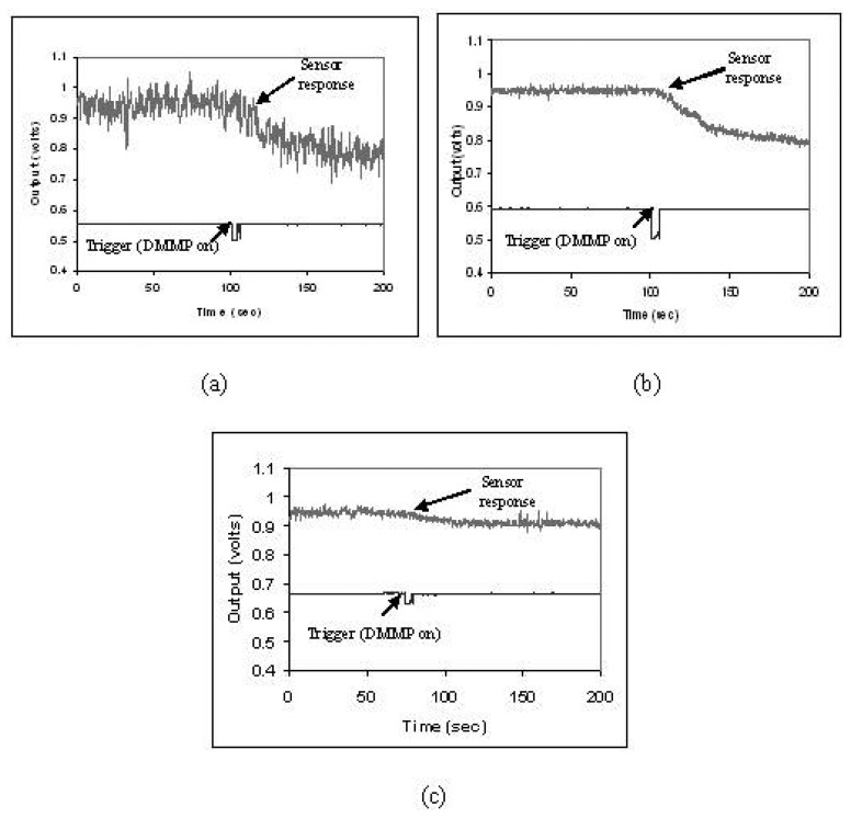
Protection of public and military personnel from chemical and biological warfareagents is an urgent and growing national security need. Along with this idea, we havedeveloped a novel class of fiber optic chemical sensors, for detection of toxic and biologicalmaterials. The design of these fiber optic sensors is based on a cladding modificationapproach. The original passive cladding of the fiber, in a small section, was removed and thefiber core was coated with a chemical sensitive material. Any change in the opticalproperties of the modified cladding material, due to the presence of a specific chemicalvapor, changes the transmission properties of the fiber and result in modal powerredistribution in multimode fibers. Both total intensity and modal power distribution (MPD)measurements were used to detect the output power change through the sensing fibers. TheMPD technique measures the power changes in the far field pattern, i.e. spatial intensitymodulation in two dimensions. Conducting polymers, such as polyaniline and polypyrrole,have been reported to undergo a reversible change in conductivity upon exposure tochemical vapors. It is found that the conductivity change is accompanied by optical propertychange in the material. Therefore, polyaniline and polypyrrole were selected as the modifiedcladding material for the detection of hydrochloride (HCl), ammonia (NH₃), hydrazine(H₄N₂), and dimethyl-methl-phosphonate (DMMP) {a nerve agent, sarin stimulant},respectively. Several sensors were prepared and successfully tested. The results showeddramatic improvement in the sensor sensitivity, when the MPD method was applied. In thispaper, an overview on the developed class of fiber optic sensors is presented and supportedwith successful achieved results.
Keywords: Biological Sensors; Chemical Sensors; Fiber Optic Sensors; Fiber Optics; Gas Sensors; Home Land Security; Sarin Detection.
Figures
References
-
- Wolfbeis O.S. Fiber optic chemical sensors and biosensors. Vol. 1&2 CRC Press; Boca Raton, Florida: 1991. 1992.
-
- Stewart G., Jin W., Culshaw B. Prospects for fiber optic evanescent field gas sensors using absorption in the near infrared. Sensors & Actuators B. 1997;38:42–47.
-
- Chan K., Ito H., Inable H. An optical fiber based gas sensor for remote adsorption measurement of low level methane gas in near infrared region. J. Lightwave Technology. 1984;2:234–237.
-
- Wolfbeis O.S., Posch H. E. Fiber optic fluorescing sensor for ammonia. Anal. Chim. Acta. 1986;185:321–327.
-
- Rowe-Taitt C.A., Ligler F. S. In: Fiber Optic Biosensors. Lopez-Higuera J.M., editor. John Wiley & Sons Ltd; 2001. pp. 687–700. Handbook of optical fiber sensing technology.
LinkOut - more resources
Full Text Sources
